Filtration device

a filtration device and filter medium technology, applied in the direction of filtration separation, separation process, manufacturing tools, etc., can solve the problems of difficult to wash the filter medium in order to recover the filtration capability, frequent replacement of chips as the filter medium, and gradual contamination of fluid, etc., to achieve high filtration accuracy and effective and thorough cleaning

Inactive Publication Date: 2011-03-17
BUNRI
View PDF2 Cites 3 Cited by
  • Summary
  • Abstract
  • Description
  • Claims
  • Application Information

AI Technical Summary

Benefits of technology

[0010]Accordingly, the object of the present invention is to provide a filtration device in which magnetic metal balls can be fully cleaned in a cleaning process.
[0012]In the cleaning process for the magnetic filter medium granules, according to this structure, air is ejected into the filtered clean fluid located above the magnetic filter medium granules and toward the magnetic filter medium granules. As the clean fluid urged by the ejected air flows down between the magnetic filter medium granules, the magnetic filter medium granules can be effectively and thoroughly cleaned. Since the filtration capability is recovered in this way, high filtration accuracy can be obtained in a filtration process.

Problems solved by technology

As the workpiece is machined, fine particles such as swarf, carbon, etc., as well as chips, become mixed in the fluid of this type, so that the fluid is gradually tainted and inevitably becomes contaminated.
Since the surfaces of the chips used as the filter medium are very rough, moreover, it is difficult to wash the filter medium in order to recover the filtration capability when the filtration capability is reduced.
Thus, there is a problem that the chips as the filter medium need to be replaced frequently.
In some cases, however, the magnetic metal balls may not be able to be fully cleaned by only pouring the fluid collected above the magnetic metal balls, so that there is room for further improvement in cleaning effect.

Method used


Image

  • Filtration device
  • Filtration device
  • Filtration device

Examples


Embodiment Construction

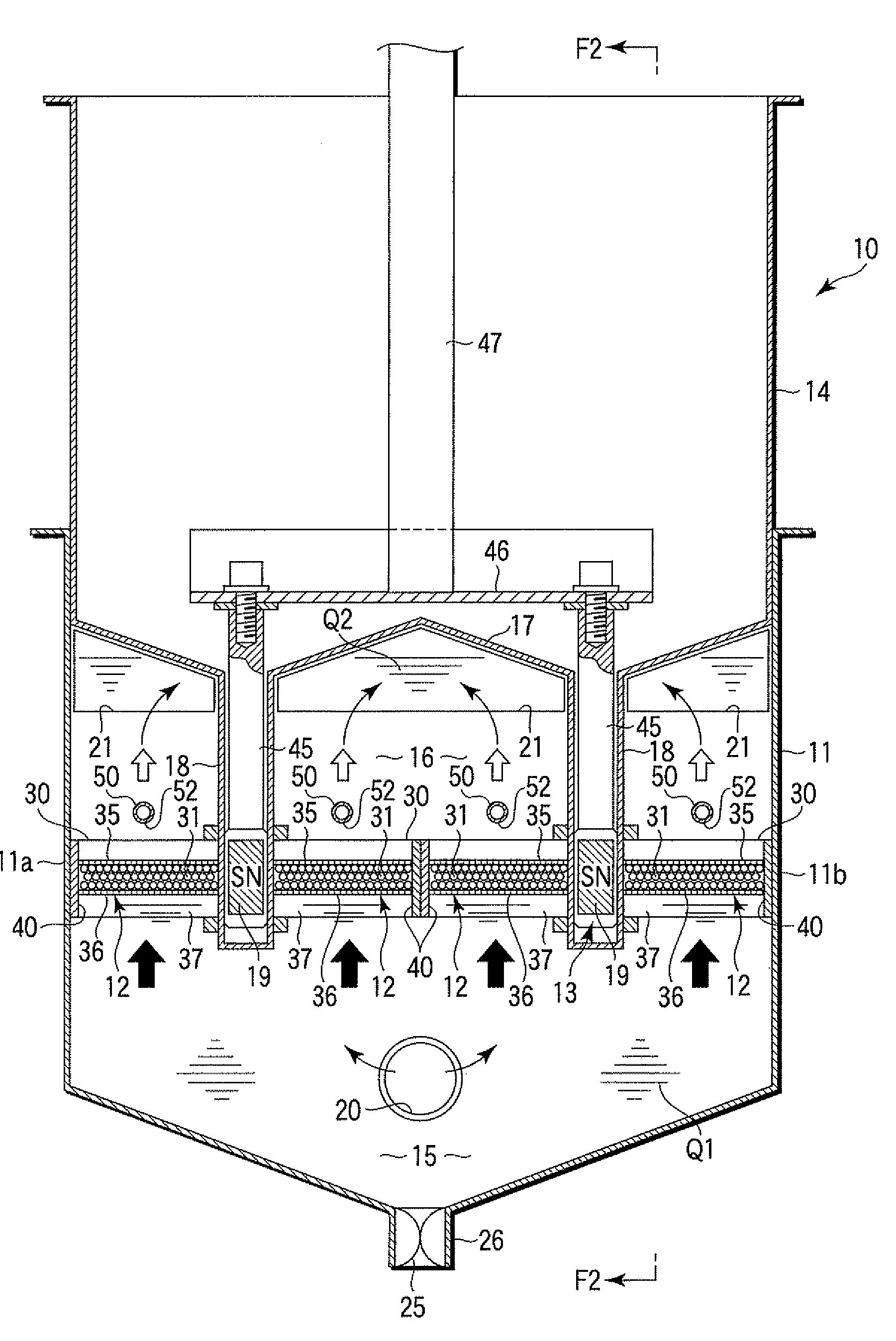
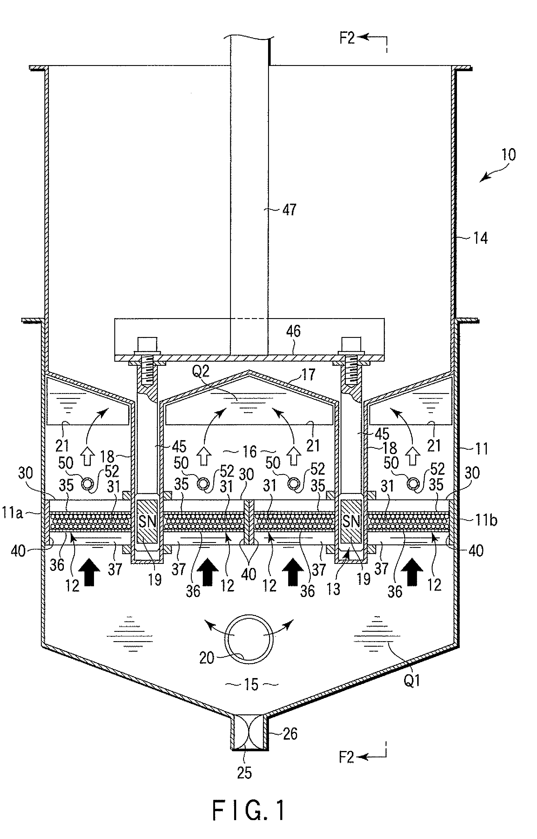
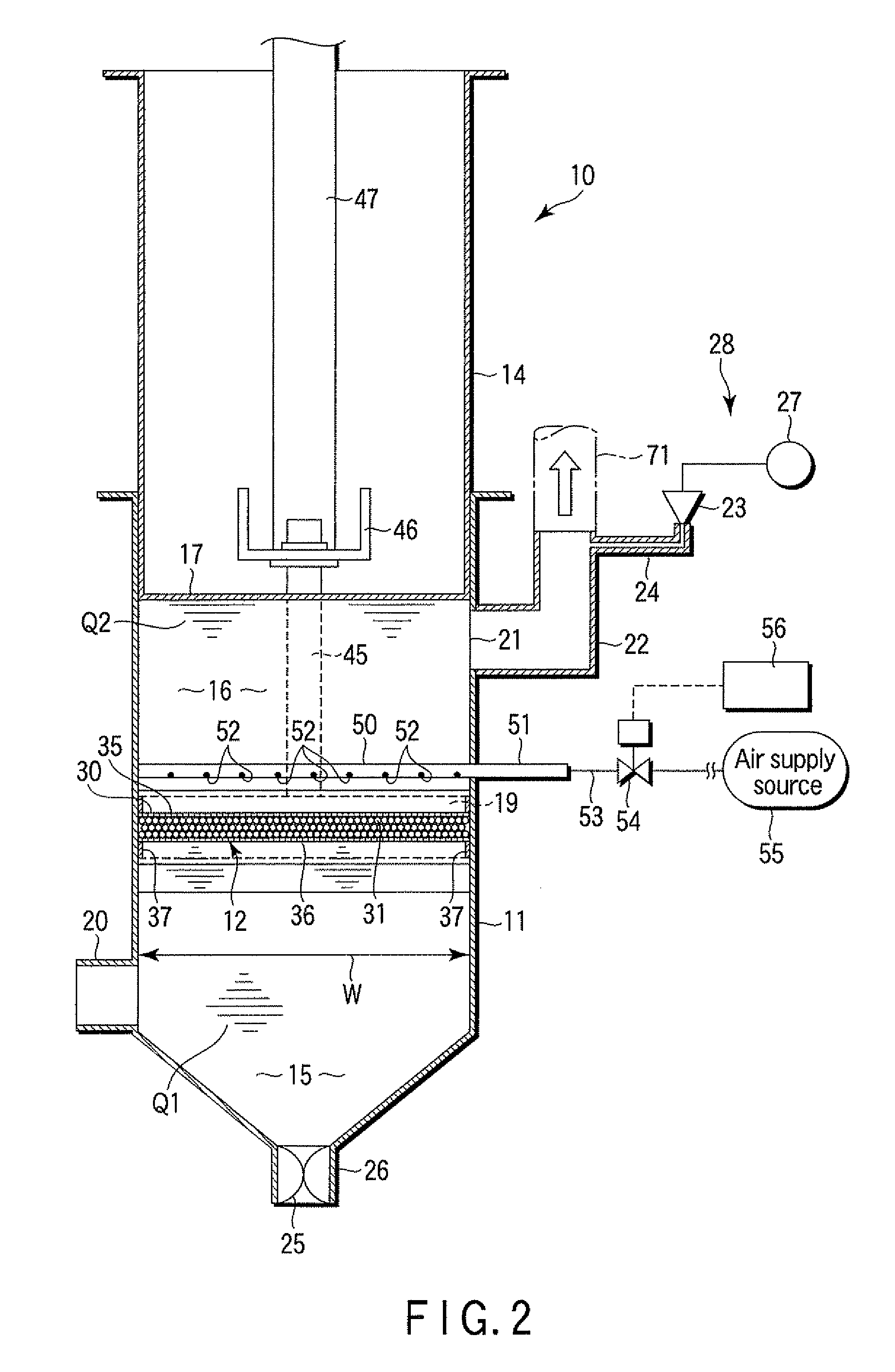
[0023]One embodiment of the present invention will now be described with reference to FIGS. 1 to 7.

[0024]A filtration device 10 shown in FIG. 1 comprises a filter tank 11, filter medium units 12, and magnet units 13. A fluid to be filtered is introduced into the filter tank 11. The filter medium units 12 are contained in the filter tank 11. The magnet units 13 apply a magnetic field to the filter medium units 12. The material of the filter tank 11 is a magnetic material, such as a ferrous metal. A cover housing 14 is disposed on top of the filter tank 11. A dirty chamber 15 and clean chamber 16 are defined in the filter tank 11. An unfiltered fluid Q1 is contained in the dirty chamber 15. A filtered clean fluid Q2 is contained in the clean chamber 16.

[0025]The dirty chamber 15 is located below the filter medium units 12. The clean chamber 16 is located above the filter medium units 12. The top of the clean chamber 16 is airtightly closed by a partition wall 17. Magnet chambers 18 ar...


PUM

PropertyMeasurementUnit
distanceaaaaaaaaaa
diameteraaaaaaaaaa
diameteraaaaaaaaaa

Abstract

A filtration device is provided with a filter tank, filter medium unit, magnet, and submerged air discharging mechanism. The filter medium unit includes a large number of magnetic filter medium granules formed of metal balls. When the magnet is in a first position, the magnetic filter medium granules magnetically attract one another. When the magnet is moved to a second position, the magnetic filter medium granules are released from the mutual magnetic attraction. In cleaning the magnetic filter medium granules, a clean fluid located above the magnetic filter medium granules is poured between the magnetic filter medium granules. In cleaning the magnetic filter medium granules, the submerged air discharging mechanism ejects air into the clean fluid above the magnetic filter medium granules and toward the magnetic filter medium granules. Air bubbles are introduced into the clean fluid by the ejected air.

Description

CROSS REFERENCE TO RELATED APPLICATIONS[0001]This is a Continuation Application of PCT Application No. PCT / JP2009 / 062744, filed Jul. 14, 2009, which was published under PCT Article 21(2) in Japanese.[0002]This application is based upon and claims the benefit of priority from prior Japanese Patent Application No. 2008-198077, filed Jul. 31, 2008, the entire contents of which are incorporated herein by reference.BACKGROUND OF THE INVENTION[0003]1. Field of the Invention[0004]The present invention relates to a filtration device for filtering a fluid containing matter to be removed, such as fine particles.[0005]2. Description of the Related Art[0006]A machine tool for precision machining, for example, uses a fluid such as a coolant for lubricating or cooling a part being machined. As the workpiece is machined, fine particles such as swarf, carbon, etc., as well as chips, become mixed in the fluid of this type, so that the fluid is gradually tainted and inevitably becomes contaminated. A...

Claims


Application Information

Patent Timeline
Patent Type & Authority Applications(United States)
IPC IPC(8): B01D35/06
CPCB01D35/06B03C1/0332B23Q11/1069B03C2201/18B03C1/286
Inventor TASHIRO, MINORU
Owner BUNRI
Why Eureka
Try Eureka