Rotor Design for an Electric Motor

a rotor and electric motor technology, applied in the field of electric motor rotor assembly, can solve the problems of inferior electrical conductivity, high manufacturing cost and complexity, etc., and achieve the effect of improving electrical and mechanical characteristics and low weigh

Active Publication Date: 2011-03-17
TESLA INC
View PDF4 Cites 26 Cited by
  • Summary
  • Abstract
  • Description
  • Claims
  • Application Information

AI Technical Summary

Benefits of technology

[0009]A rotor assembly and a method for fabricating the same are disclosed which provide a solid rotor ring located at either end of a stack of laminated discs, the solid rotor rings yielding improved electrical and mechanical ch

Problems solved by technology

Typically these techniques make trade-offs between several, often competing, factors that include (i) maximizing the electrical conductivity between the rotor bars; (ii) rotor weight; (iii) material cost; and (iv) fabrication/assembly cost and complexity.
Frictional heating causes the ends of the rotor bar

Method used


Image

  • Rotor Design for an Electric Motor
  • Rotor Design for an Electric Motor
  • Rotor Design for an Electric Motor

Examples


Embodiment Construction

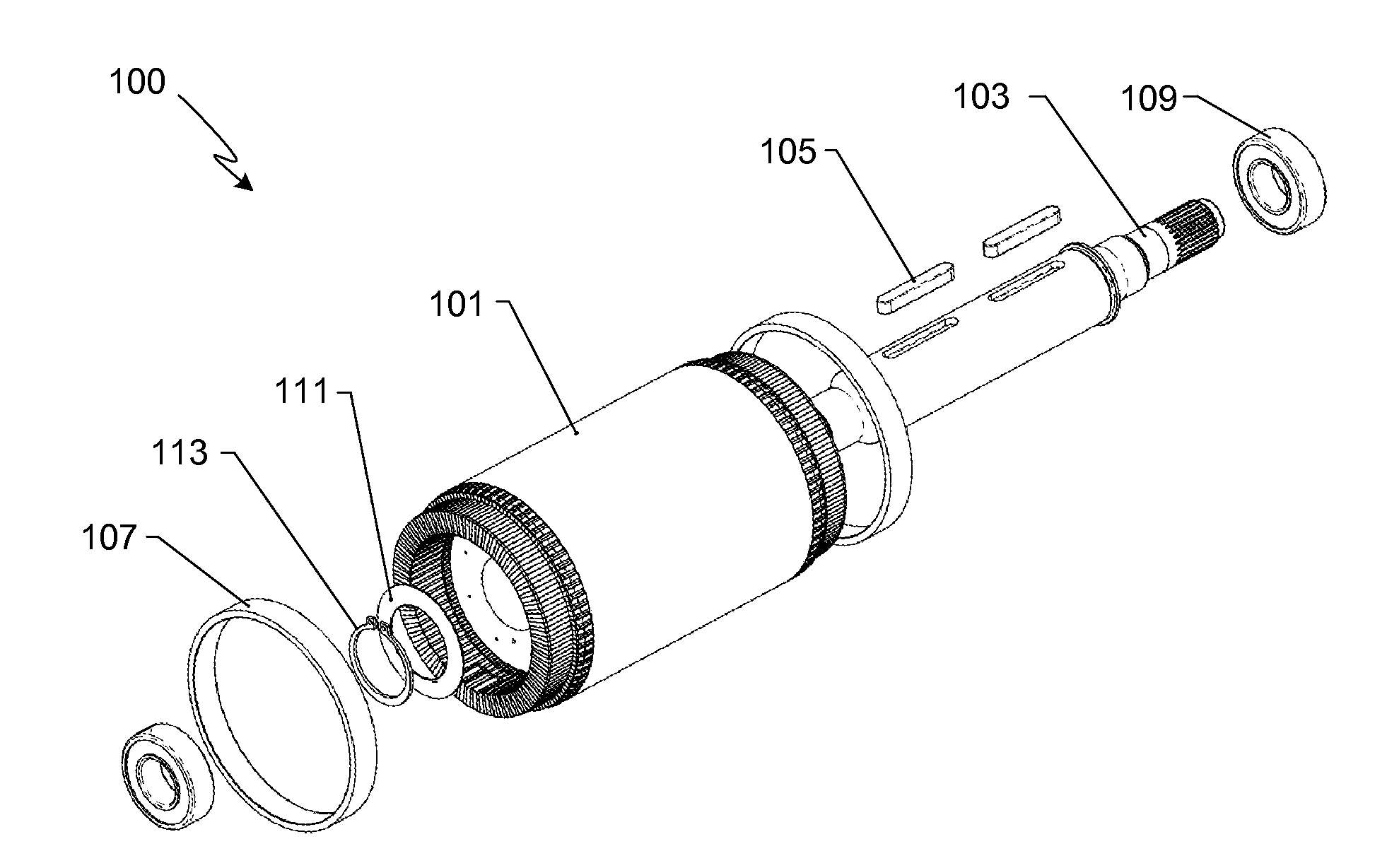
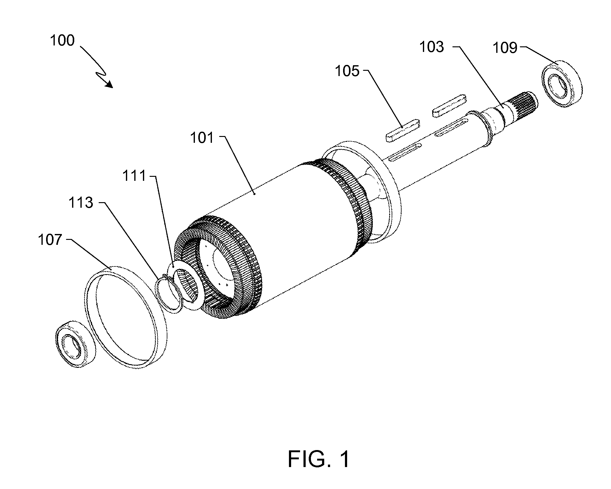
[0025]FIG. 1 is an exploded, perspective view of the primary components of a rotor assembly 100 in accordance with a preferred embodiment of the invention. It will be appreciated that other configurations may be used with the invention, and the specific designs and dimensions provided relative to the preferred embodiment are only meant to illustrate, not limit, the invention.

[0026]As described in further detail below, the core assembly 101 is comprised of a plurality of laminated discs, a plurality of conductor bars (also referred to herein as rotor bars), and a plurality of slugs that are positioned between, and brazed to, the end portions of the conductor bars. Core assembly 101 is coaxially mounted to a rotor shaft 103, shaft 103 preferably including keys 105, or similar means, for locating and positioning the core assembly about its central axis. At either end of core assembly 101 is a rotor containment ring 107. Additionally, and as shown in FIG. 1, rotor assembly 100 includes ...


PUM

PropertyMeasurementUnit
Fractionaaaaaaaaaa
Fractionaaaaaaaaaa
Fractionaaaaaaaaaa

Abstract

A rotor assembly and a method for fabricating the same are provided in which a solid rotor ring is formed at either end of a stack of laminated discs, the solid rotor rings yielding improved electrical and mechanical characteristics in a low weight assembly. The solid rotor rings are fabricated by brazing slugs between the end portions of the rotor bars, the braze joints contacting a large percentage (at least 90%) of the rotor bar end portions.

Description

CROSS-REFERENCE TO RELATED APPLICATION[0001]This application is a continuation-in-part of U.S. patent application Ser. No. 11 / 452,793, filed Jun. 13, 2006, the disclosure of which is incorporated herein by reference for any and all purposes.FIELD OF THE INVENTION[0002]The present invention relates generally to electric motors and, more specifically, to an electric motor rotor assembly.BACKGROUND OF THE INVENTION[0003]AC induction motors are widely used in a variety of industrial and residential applications. In general, this type of motor includes a laminated magnetic core mounted to a drive shaft. The laminated magnetic core may be fabricated from a plurality of laminated magnetic discs, or from a plurality of arc-like core segments. The laminated magnetic core includes a plurality of longitudinal slots into which bars of electrically conductive metal are fit. The ends of the bars extend beyond either end of the laminated magnetic core. An end-ring or end-cap at either end of the l...

Claims


Application Information

Patent Timeline
IPC IPC(8): H02K1/22H02K15/02
CPCH02K15/0012H02K15/0081Y10T29/49012Y10T29/49009H02K17/165
Inventor LYONS, DAVIDSTRAUBEL, JEFFREY B.SHAHOIAN, ERIKGARRIGA, RUDY
Owner TESLA INC
Why Eureka
Try Eureka