Intergrated magnetic component

a magnetic component and integrated technology, applied in the field of magnetic components, can solve the problems of affecting efficiency, dictating the size and electrical performance of the components, affecting reliability and costs, and higher size and costs, so as to reduce costs and improve efficiency.

Active Publication Date: 2011-03-17
DELTA ELECTRONICS (THAILAND) PUBLIC CO LTD +1
View PDF20 Cites 45 Cited by
  • Summary
  • Abstract
  • Description
  • Claims
  • Application Information

AI Technical Summary

Benefits of technology

[0010]It is the object of the invention to create a magnetic component pertaining to the technical field initially mentioned that reduces costs and improves efficiency.

Problems solved by technology

Switched mode power supplies as main part of telecom and commercial systems often dictate their size and electrical performance as well as reliability and costs.
This configuration results, additionally to the number of discrete magnetic components which yield higher size and costs, in three high current windings and several high interconnection losses which negatively impact the efficiency.
This converter results, additionally to the number of discrete magnetic components which yield higher size and costs, in at least three windings and several interconnections which negatively impact the efficiency.
The reduction of the number of secondary windings and high current interconnections result in lower winding losses.
While the described patents address some proposed ameliorations, there are still some setbacks.
These cores are not flexible in term of mounting and of adjusting the magnetizing inductance and filtering inductance through air gap.
Generally a single air gap is manufactured on the centre leg by machine and bobbins are unavoidable to wind the coils.
The single air gap, the bobbin and the inflexible assembly negatively affect the costs, the power density, the power efficiency and the thermal distribution.
There are supplementary power losses due to air gap fringing fields and higher winding mean length.
The bobbins and single air gap are costly and cause more leakage and inductance losses.

Method used


Image

  • Intergrated magnetic component
  • Intergrated magnetic component
  • Intergrated magnetic component

Examples


Embodiment Construction

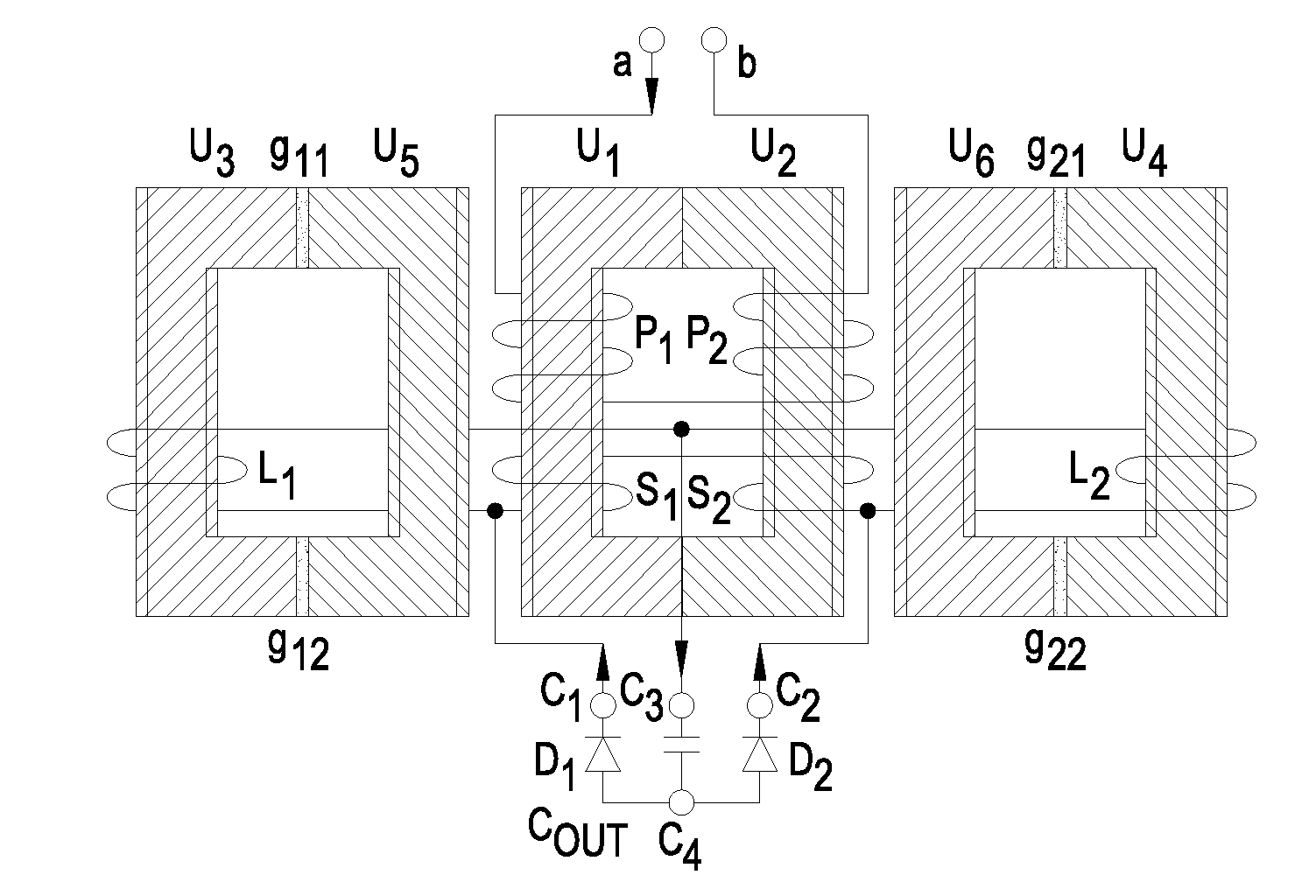
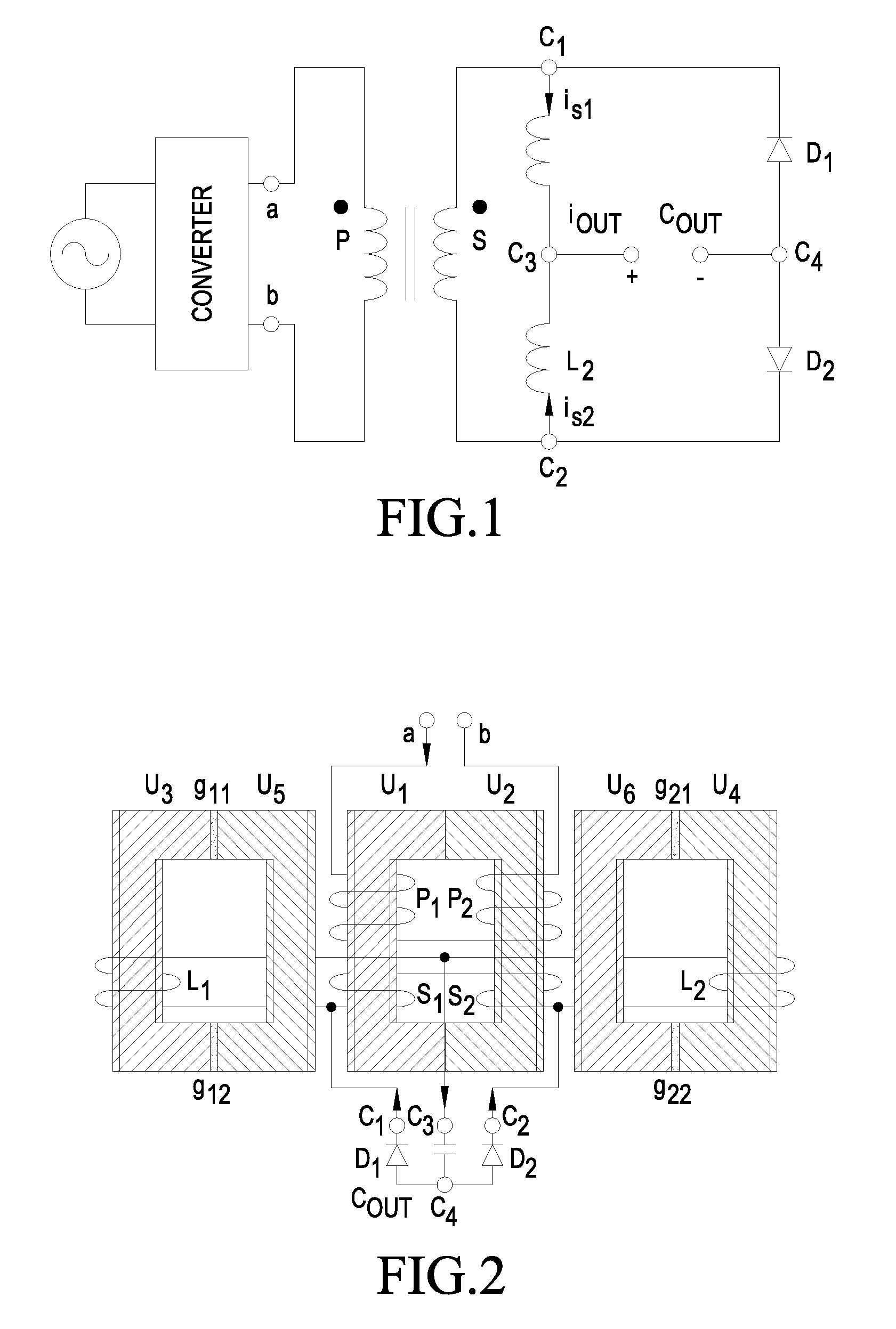
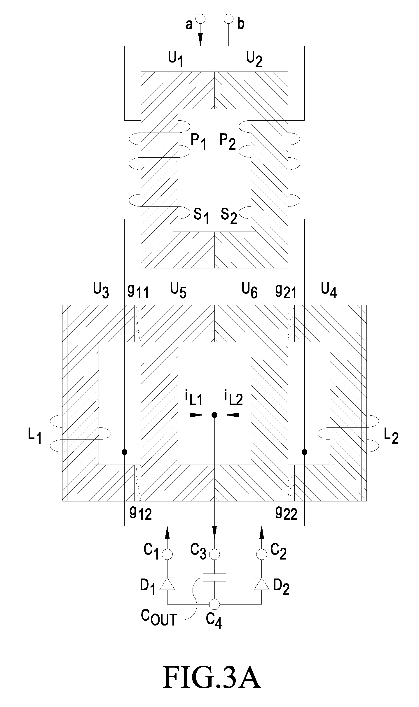
[0115]The present invention provides integrated magnetic structures using bobbin less U / UR cores on whose leg the windings are directly wound. The tight core-winding coupling yields lower leakage and minimized copper power losses and inductance losses. Moreover the power density increases and the cost are reduced with the absence of bobbins. The U / UR cores are used as building blocks which make their assembly more flexible. Air gaps don't need to be ground and are inserted at connection points between U / UR cores in order to adjust the reluctances and thus the magnetizing and filtering inductances. Also due to mechanical stability, air gap are being distributed which engenders reduced AC winding power losses and minimized inductance losses caused by air gap fringing fields. The core structure can either be fully composed of high permeability low saturation cores with air gaps or be composite comprising low permeability high saturation cores and high permeability low saturation cores ...


PUM

PropertyMeasurementUnit
permeabilityaaaaaaaaaa
saturation flux densityaaaaaaaaaa
magneticaaaaaaaaaa

Abstract

A magnetic component, with a first and a second U/UR core (U1, U2) assembled to a first O-shaped core assembly, wherein an U/UR core has—according to its shape—a first post and a second post with free ends on one side and a leg connecting the first post and the second post on their other side, wherein the first and the second U/UR core (U1, U2) are assembled with their free ends abutting each other to form the first O-shaped core assembly. The free ends of a third U/UR core (U3) are abutting the outside of the first O-shaped core assembly on one side and that the free ends of a fourth U/UR core (U4) are abutting the outside of the first O-shaped core assembly on an opposite side. In another embodiment, the leg of a third U/UR core (U3) is abutting the outside of the first O-shaped core assembly, wherein the ends of a fourth U/UR core (U4) are abutting the ends of the third U/UR core (U3). In a further embodiment, the ends of a third U/UR core (U3) are abutting the outside of the first O-shaped core assembly. At least one winding is wound directly on the first, the second, the third, and/or the fourth U/UR core (U1, U2, U3, U4). The core structure can either be fully composed of high permeability low saturation cores with air gaps or be composite comprising low permeability high saturation cores and high permeability low saturation cores with no air gaps.

Description

TECHNICAL FIELD[0001]The invention relates to a magnetic component. The invention relates particularly to an integrated magnetic component for switched mode power converters and specifically to DC / DC power converters.BACKGROUND ART[0002]Switched mode power supplies as main part of telecom and commercial systems often dictate their size and electrical performance as well as reliability and costs. As requirements for the key characteristics power density and efficiency of power converters increase, the demands of these evaluation characteristics increase for inductive components particularly. One approach of increasing the power density and the efficiency is to integrate the inductive components. Transformers and inductors can be integrated into a single magnetic structure, which reduces costs, increases power density and power efficiency.[0003]A circuit where integrated magnetics is strongly recommended is the current-doubler rectifier (FIG. 1), which can be used with different doubl...

Claims


Application Information

Patent Timeline
Patent Type & Authority Applications(United States)
IPC IPC(8): H01F27/28H01F17/04H01F41/00
CPCH01F3/10H01F3/14H01F27/306H01F27/38Y10T29/49071H01F30/10H01F41/02H02M3/28H01F27/40
Inventor HUGUES DOUGLAS, NJIENDE T.ROLAND, ROBRECHTJOCHEN, MIELKE
Owner DELTA ELECTRONICS (THAILAND) PUBLIC CO LTD
Why Eureka
Try Eureka