Device and method for controlling azimuth beamwidth across a wide frequency range

a beamwidth and wide frequency range technology, applied in waveguide-type devices, electrical equipment, independent non-interacting antenna combinations, etc., can solve the problems of large variation in gain response, antennae that can operate across a wide frequency band have difficulty maintaining a reasonable beamwidth across their full frequency range, and are not suited to deploying networks in the higher bands

Inactive Publication Date: 2011-03-17
JAYBEAM UK
View PDF13 Cites 37 Cited by
  • Summary
  • Abstract
  • Description
  • Claims
  • Application Information

AI Technical Summary

Benefits of technology

[0016]To resolve at least the problems discussed above, it is an object of the present invention to provide a system and method for maintaining a compact azimuth beamwidth in a wide band antenna. The system comprises a first radiating element disposed above a ground plane and one or more parasitic elements disposed proximate to and/or around the first radiating element. Each of the parasitic elements has a slot formed therein that is configured to control beamwidth across a specific frequency range. In one embodiment, the parasitic elements and the slots are configured to ...

Problems solved by technology

But as the bandwidth of the antenna increases, physics dictate that the range of values of the azimuth beamwidth will also increase, which results in a large variation in gain response.
Thus, antennae that can operate across a wide frequency band have difficulty maintaining a reasonable beamwidth ...

Method used


Image

  • Device and method for controlling azimuth beamwidth across a wide frequency range
  • Device and method for controlling azimuth beamwidth across a wide frequency range
  • Device and method for controlling azimuth beamwidth across a wide frequency range

Examples


Embodiment Construction

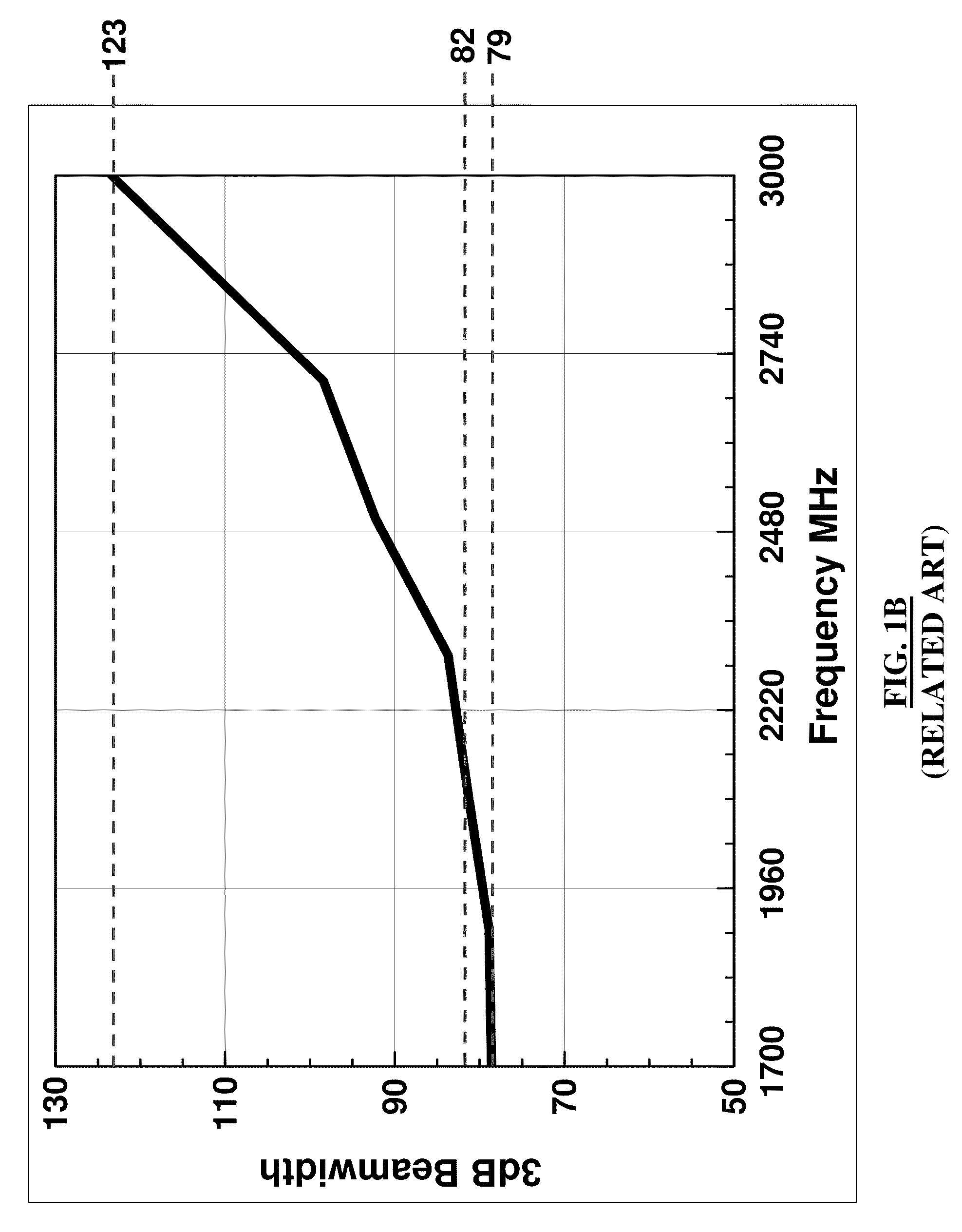
[0039]Wireless communication networks currently deployed in the 1700-2200 MHz (e.g., AWS, DCS, and PCS networks) operate with bandwidth a 24%. And when that frequency range is expanded to include networks that operate with frequencies as high as 2690 MHz (e.g., IMT-E networks), the bandwidth increases to 46%. The present invention goes even further by providing a wide bandwidth antenna that maintains a uniform azimuth beamwidth and, therefore, flatter gain response across a 55% bandwidth. In the embodiments described below, that 55% beamwidth is described primarily as being provided by the 2200-3000 MHz frequency range. However, it will be understood by those having ordinary skill in the art that those embodiments can be modified to provide similar performance enhancements in other frequency ranges without departing from the spirit of the present invention.

[0040]The technology of the present invention offers great flexibility in antenna sharing, network deployment, and logistic plan...


PUM

PropertyMeasurementUnit
Fractionaaaaaaaaaa
Angleaaaaaaaaaa
Frequencyaaaaaaaaaa

Abstract

A system and method for providing a compact azimuth beamwidth in a wide band antenna. The system comprises a first radiating element disposed above a ground plane and one or more parasitic elements disposed proximate to and/or around the first radiating element. Each of the parasitic elements has a slot formed therein that is configured to control beamwidth across a specific frequency range. In one embodiment, the parasitic elements and the slots can be configured to control beamwidth across different frequency ranges. And in another embodiment, another parasitic element is disposed within the slots to control beamwidth across another frequency range.

Description

CROSS-REFERENCE TO RELATED APPLICATIONS[0001]This application claims the benefit of U.S. Provisional Application Ser. No. 61 / 237,060, filed Aug. 26, 2010, the entire disclosure of which is hereby incorporated by reference.BACKGROUND OF THE INVENTION[0002]1. Field of the Invention[0003]The present invention relates to devices and methods for controlling azimuth beamwidth across a wide frequency range. In particular, the present invention relates to parasitic elements that allow an antenna or an array of antennae to maintain a flat azimuth beamwidth across a broad bandwidth, especially when used in base station applications.[0004]2. Description of the Related Art[0005]Wireless communication networks, such as cellular phone networks, provide broadband, digital voice, messaging, and data services to mobile communication devices, such as cellular phones. Those wireless networks use the Ultra High Frequency (UHF) portion of the radio frequency spectrum to transmit and receive signals. The...

Claims


Application Information

Patent Timeline
IPC IPC(8): H01Q15/14H01P11/00
CPCH01Q1/526H01Q19/108Y10T29/49016H01Q21/28H01Q21/30H01Q21/26H01Q1/246H01Q19/005H01Q21/29
Inventor HO, JIMMYMUNDAY, SIMON CHRISTOPHER R.SAILOPAL, CHARANJITBOARDMAN, DAVID HAROLDTALBOT, BARRY JOHNKLINKOSZ, MICHAL
Owner JAYBEAM UK
Why Eureka
Try Eureka