Disk drive device capable of being improved in Anti-vibration characteristic

a technology of anti-vibration and drive device, which is applied in the direction of recording information storage, manufacturing tools, instruments, etc., can solve the problems of reducing the bearing stiffness of the fluid dynamic bearing unit, increasing the error of reading/writing data, etc., and achieves the effect of efficient radial dynamic pressure increas

Inactive Publication Date: 2011-03-17
SAMSUNG ELECTRO MECHANICS JAPAN ADVANCED TECHNOLOGY CO LTD
View PDF6 Cites 19 Cited by
  • Summary
  • Abstract
  • Description
  • Claims
  • Application Information

AI Technical Summary

Benefits of technology

[0010]By making the width in the rotational direction of the intermediate portion in a striped groove portion narrower than that in the rotational direction of each of the end portions on both sides, it becomes possible that an amount of lubricant, which is larger than that acceptable with the intermediate portion, can be scraped up from the end portions to be transferred into the intermediate portion, thereby allowing for radial dynamic pressure to be efficiently increased.

Problems solved by technology

If a drive current in a disk drive device is reduced, the dynamic pressure to be generated by a fluid dynamic bearing unit is decreased accordingly, resulting in decreased bearing stiffness of the fluid dynamic bearing unit.
If a displacement of a recording disk becomes large, the relative distance between the recording disk and a magnetic head becomes unstable, thereby causing the problem that an increase in errors in reading / writing data may be incurred.

Method used


Image

  • Disk drive device capable of being improved in Anti-vibration characteristic
  • Disk drive device capable of being improved in Anti-vibration characteristic
  • Disk drive device capable of being improved in Anti-vibration characteristic

Examples


Embodiment Construction

[0021]The invention will now be described by reference to the preferred embodiments. This does not intend to limit the scope of the present invention, but to exemplify the invention.

[0022]Hereinafter, preferred embodiments of the present invention will be described based on the accompanying drawings. The present embodiment can be adopted in a brushless motor, which is mounted in a Hard Disk Drive device (sometimes, simply referred to as an HDD or a disk drive device) to drive a recording disk, or adopted in a disk drive motor to be mounted in an optical disk recording and reproducing device, such as a CD (Compact Disc) device and a DVD (Digital Versatile Disc) device.

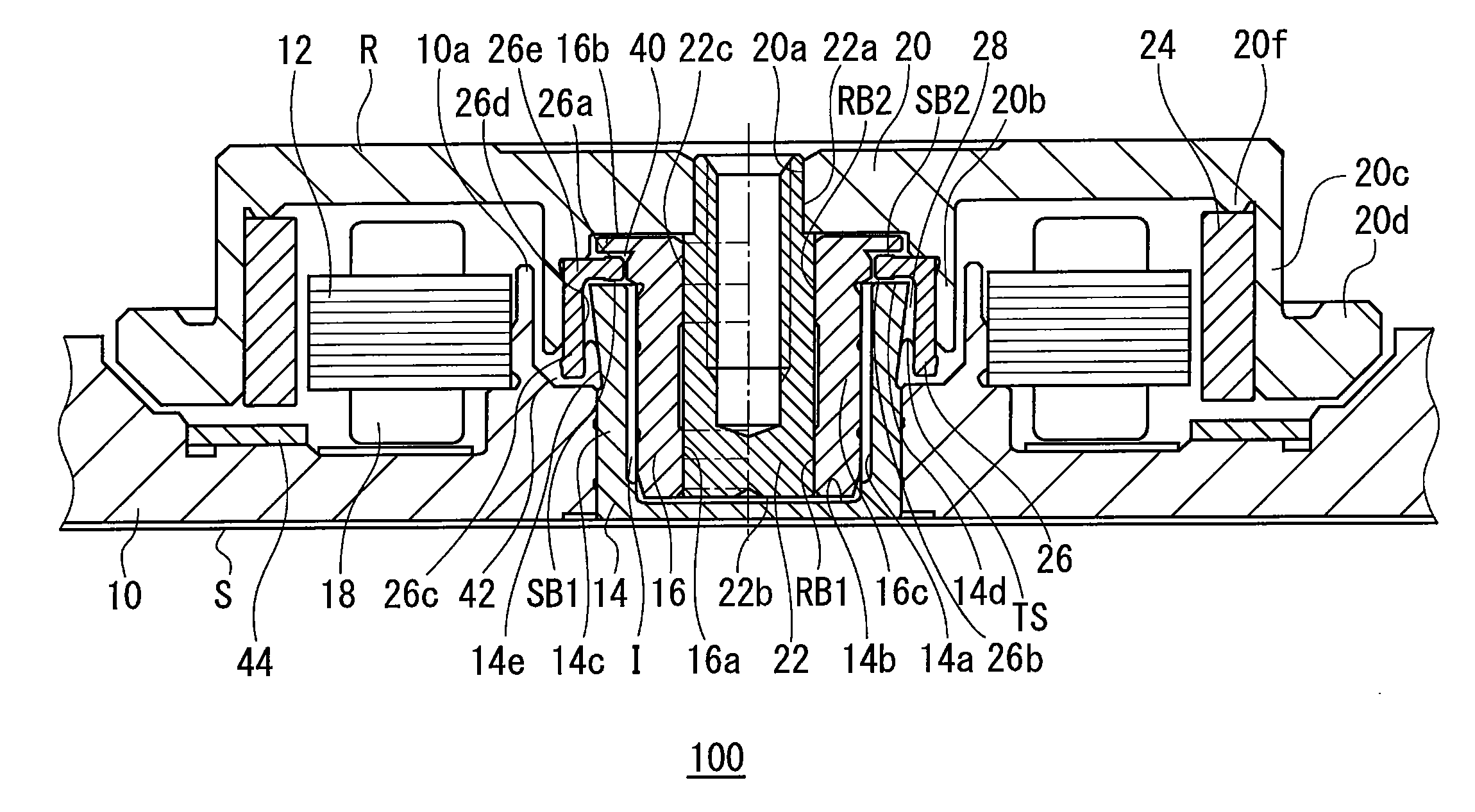
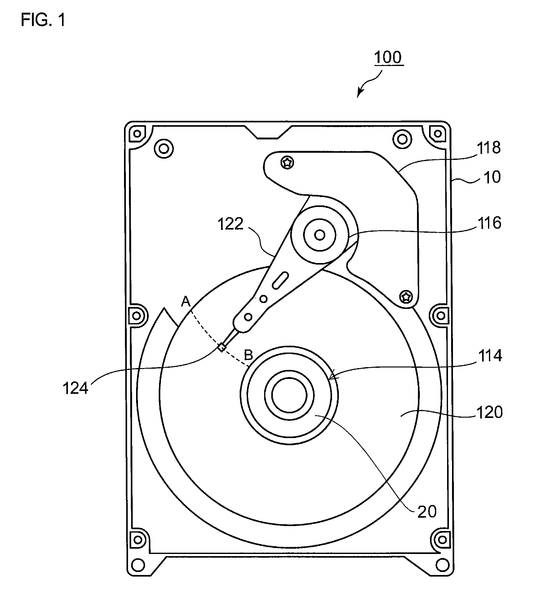
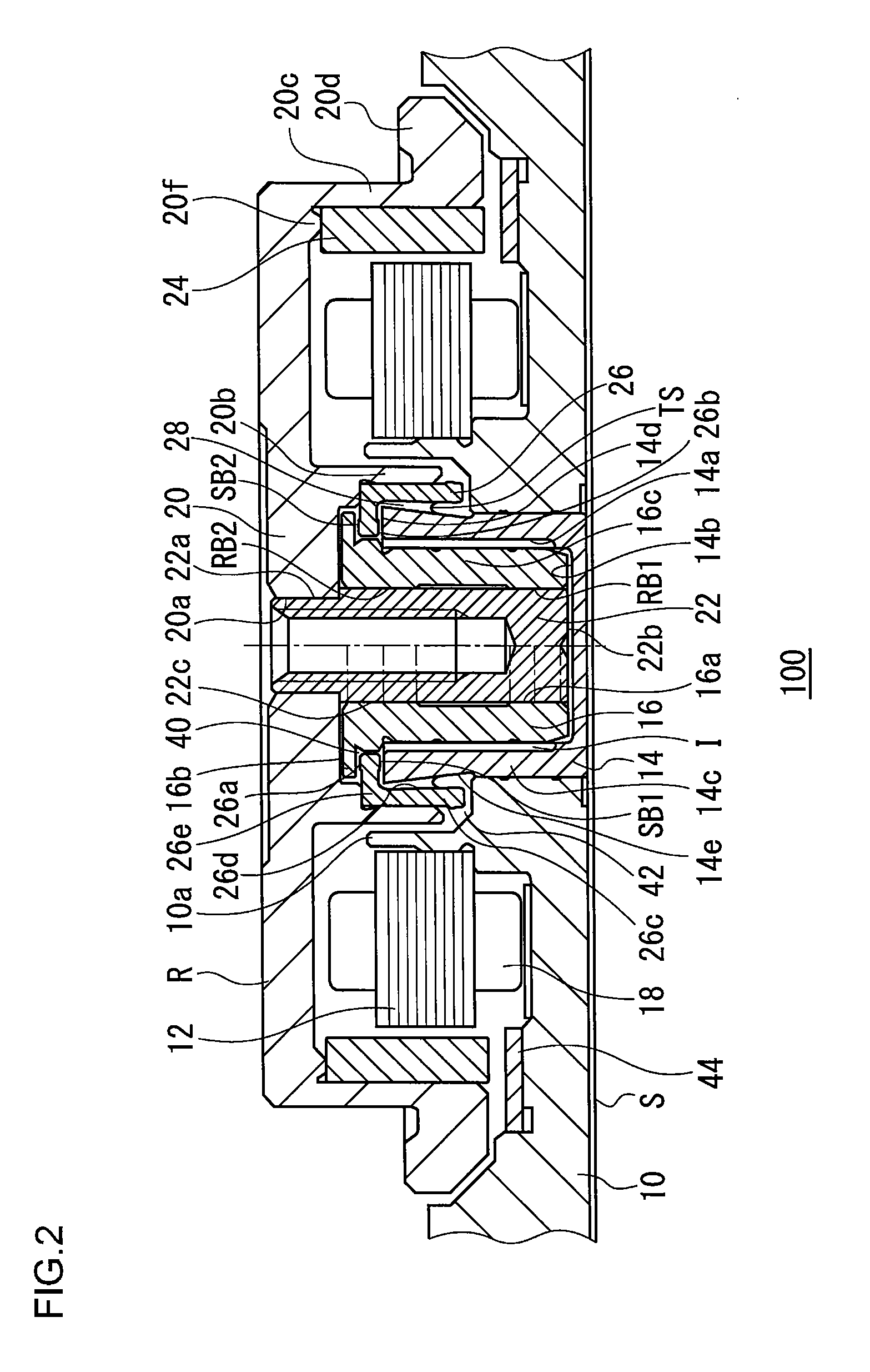
[0023]FIG. 1 is an illustrative view illustrating the internal structure of an HDD 100 (hereinafter, referred to as a disk drive device 100), which is an example of a disk drive device according to the present embodiment. FIG. 1 illustrates the state where a cover is removed to expose the internal structure.

[0024]A brus...


PUM

PropertyMeasurementUnit
diameteraaaaaaaaaa
circumferential width Pgaaaaaaaaaa
circumferential widths Pgaaaaaaaaaa

Abstract

A disk drive device includes: a hub on which a recording disk is to be mounted; a shaft; a sleeve configured to house the shaft and to be rotatable relatively with respect to the shaft; a radial space portion formed between the inner circumferential surface of the sleeve and the outer circumferential surface of the shaft; a radial dynamic pressure generating portion configured to generate radial dynamic pressure between at least part of the inner circumferential surface of the sleeve and the outer circumferential surface of the shaft in the radial space portion; and lubricant. The axial length of the radial dynamic pressure generating portion is formed to be longer than the diameter of the radial dynamic pressure generating portion such that radial dynamic pressure, which is defined with the axial length of the radial dynamic pressure generating portion and the diameter thereof being parameters, is greater than or equal to a predetermined minimum reference value.

Description

BACKGROUND OF THE INVENTION[0001]1. Field of the Invention[0002]The present invention relates to a disk drive device, in particular, to a disk drive device capable of being improved in anti-vibration characteristic while reducing a drive current.[0003]2. Description of the Related Art[0004]In recent years, disk drive devices, such as Hard Disk Drives (HDDs), have been developed to be small in size and large in capacity, and been widely used in many electrical appliances. Therefore, disk drive devices have been used in a wide variety of environments. In particular, the disk drive devices are being mounted in portable devices called mobile devices. Mobile devices are frequently used in environments with a lot of vibrations, and therefore the disk drive devices to be mounted in the mobile devices are demanded to have characteristics in which read / write of data can be stably performed even when used in an environment with a lot of vibrations. In order to meet such a demand, there is a d...

Claims


Application Information

Patent Timeline
Patent Type & Authority Applications(United States)
IPC IPC(8): G11B17/02F16C32/06B26D1/00H04R17/00B23B3/00
CPCB23B5/00B23B2260/108F16C17/026F16C17/107F16C33/107Y10T82/10F16C2240/40G11B19/2036F16C2370/12Y10T29/42F16C33/745Y10T83/04
Inventor MIZUNO, MASAFUMIKODAMA, MITSUOIWAI, HIROSHI
Owner SAMSUNG ELECTRO MECHANICS JAPAN ADVANCED TECHNOLOGY CO LTD
Why Eureka
Try Eureka