
Wind Oscillator for Power Generation

a technology of wind turbines and oscillators, which is applied in the direction of wind turbines, motors, machines/engines, etc., can solve the problems of difficult to maximize the effective aerodynamic surface of rotating blades, limited effective aerodynamic area, and considerable amount of aerodynamic torque generated, etc., to achieve high aerodynamic efficiency, easy expansion of effective wing areas, and cost-effective

Inactive Publication Date: 2011-03-17
WESTERN MICHIGAN UNIVERSITY
View PDF10 Cites 25 Cited by
  • Summary
  • Abstract
  • Description
  • Claims
  • Application Information

AI Technical Summary

Benefits of technology

[0010]Compared to conventional wind turbines, the invention has distinct advantages. The aerodynamic forces on the entire wing surfaces can be almost uniformly utilized, and the effective wing area can be easily enlarged, while the wing weight is not a critical concern in this design. Therefore, the aerodynamic efficiency is high.
[0011]In addition, rectangular shaped wings are typically used, and the structural and geometrical simplicity of the wings makes manufacturing of the wings cost-efficient. The structurally and geometrically simple wing arrangement, and mounting the major mechanical and electrical equipment on the ground, allows for easy installation and maintenance. Although the proposed research mainly targets medium and large size wind turbines, the design is also feasible for small size systems.

Problems solved by technology

Thus, it is difficult to maximize the effective aerodynamic surface of rotating blades, while maintaining the structural integrity thereof, as the size of a wind turbine increases.
Thus, the effective aerodynamic area is very limited near the tip of a blade where a considerable amount of aerodynamic torque is generated.
This arrangement not only adds a weight penalty on a slender blade, but also increase the structural complexity and weaken the structural integrity of the blade.
Furthermore, the installation and maintenance of long slender blades in large-size HAWT and VAWT is particularly difficult, and requires special equipment that may not be easily operated in certain terrain.
For example, contamination of dead bugs and birds near the leading edges of blades could reduce the aerodynamic efficiency by 50%.
Cleaning the contamination on blades of a large-size HAWT is not an easy task at all.
These problems become bottlenecks in the development and cost-efficient use of medium and large size wind turbines.

Method used


Image

  • Wind Oscillator for Power Generation
  • Wind Oscillator for Power Generation
  • Wind Oscillator for Power Generation

Examples


Embodiment Construction

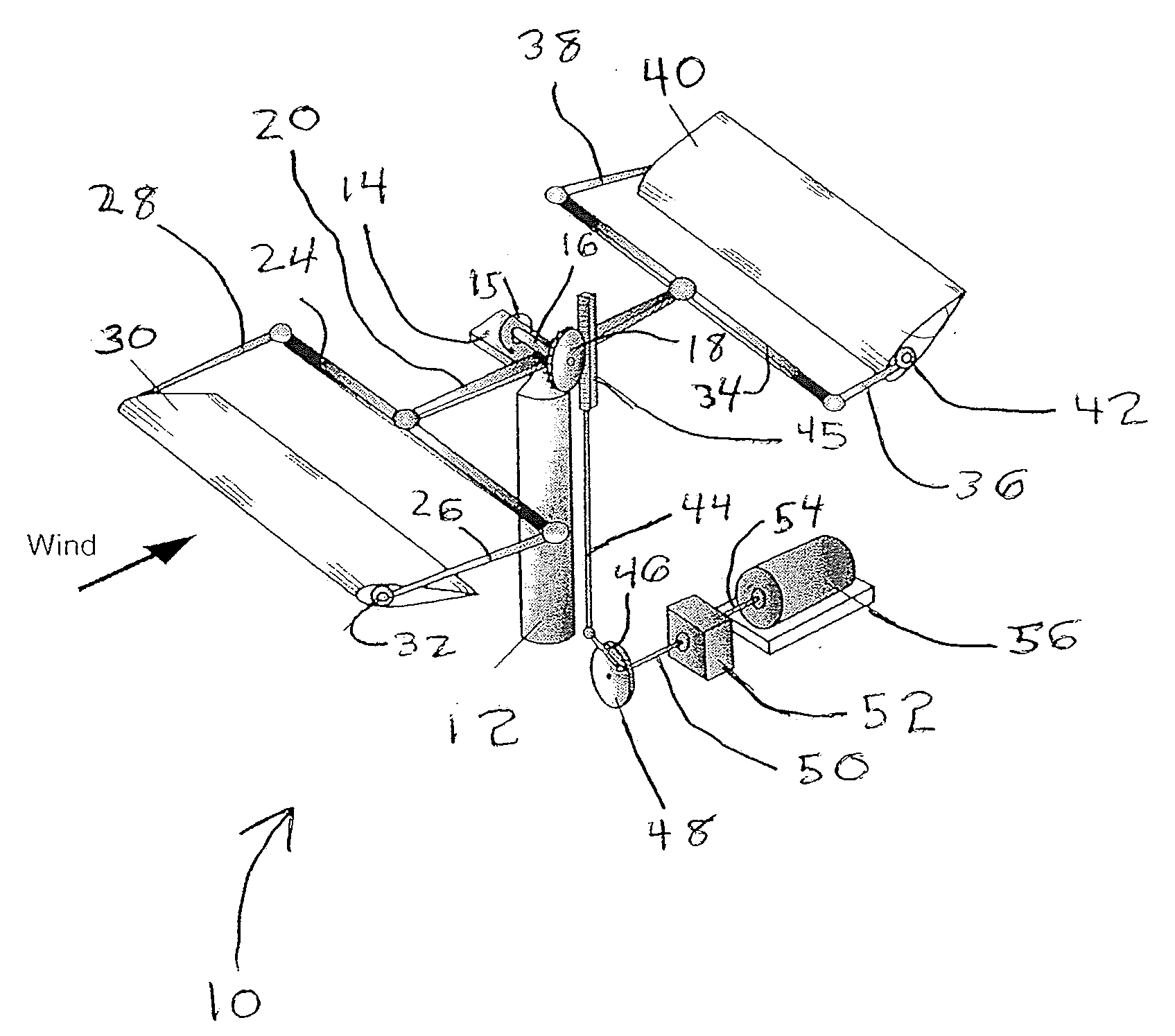
[0024]FIG. 1 shows a wind oscillator 10 including an upwardly oriented elongate rotatable support beam 12 that supports a bracket 14 that extends transversely and outwardly therefrom. The support beam 12 is generally rotatable to enable the wind oscillator 10 to remain oriented properly with respect to wind direction. A shaft 16 is joined with bracket 14 by a spring 15 disposed at a first end thereof. A second end of the shaft 16 has a toothed gear wheel 18 integrally secured thereto and rotatable therewith. The shaft 16 is disposed upon a main elongate oscillating arm 20. The oscillating arm 20 is disposed between the shaft 16 and the upward end or top of the support beam 12. The oscillating arm 20 is pivotably disposed at the top of the support beam 12 and movable upwardly and downwardly at ends thereof in a reciprocating or oscillating arrangement. The top of the support beam 12 is tapered to enable the upward and downward pivoting movement of the oscillating arm 20 disposed esse...


PUM


Abstract

A wind oscillator configured for power generation is provided. The wind oscillator includes an upwardly oriented elongate rotatable support beam configured to rotate to enable the wind oscillator to be approximately oriented with respect to a wind direction, a bracket supported by the support beam, the bracket extending transversely and outward therefrom, a shaft operably connected to the bracket at a first end of the shaft, and a gear attached to a second end of the shaft. The wind oscillator further includes an oscillating arm pivotably disposed approximately atop of said support beam, wherein the shaft is disposed upon the oscillating arm, and the oscillating arm being configured to move upwardly and downwardly with respect to the support beam in a reciprocating arrangement, an elongate transverse bar supported by a first end of the oscillating arm, elongate first and second wing bars oriented transversely with respect to the elongate transverse bar, wherein the oscillating arm, the elongate transverse bar, and the wing bars are on approximately a same plane, and a leading wing rotatably connected to and extending between the first and second wing bars.

Description

CROSS REFERENCE TO RELATED APPLICATIONS[0001]This application claims priority under 35 U.S.C. §119(e) to U.S. Provisional Patent Application No. 61 / 276,871, filed on Sep. 17, 2009, by Tianshu Liu, the entire disclosure of which is hereby incorporated herein by reference.FIELD OF THE INVENTION[0002]The invention is directed to a wind oscillator for generating electrical energy.BACKGROUND OF THE INVENTION[0003]Wind energy, as a major sustainable clean energy source, has recently attracted an intense amount of attention. Government and industry have aggressively pushed the development of wind turbine technology, particularly devoted to the development of a wide range of reliable wind turbines.[0004]In the long history of the use of wind kinetic energy, horizontal-axis wind turbines (HAWT) and vertical-axis wind turbines (VAWT) have been adopted as the main designs for extracting wind energy. In particular, HAWT is predominantly used for commercial power generation. The efficiency of tu...

Claims


Application Information

Patent Timeline
Patent Type & Authority Applications(United States)
IPC IPC(8): F03D5/06
CPCY02E10/70F03D5/06
Inventor LIU, TIANSHU
Owner WESTERN MICHIGAN UNIVERSITY
Learn More