Method of molding complex composite parts using pre-plied multi-directional continuous fiber laminate

a technology of continuous fiber and composite parts, applied in the field of methods, can solve the problems of long and costly process of lay-up procedure using ud tape, unsuitable unidirectional tape for use as molding compound, and inability to manufacture complex three-dimensional parts using ud tap

Active Publication Date: 2011-03-17
HEXCEL
View PDF6 Cites 77 Cited by
  • Summary
  • Abstract
  • Description
  • Claims
  • Application Information

AI Technical Summary

Benefits of technology

[0010]In accordance with the present invention, it was discovered that unidirectional (UD) tape can be formed into a pre-plied, multi-directional laminate that can be processed to be suitable for molding. The pre-plied laminate is formed by taking individual layers of UD tape and placing them on top of each other so that the layers or plies of the laminate contain fibers extending in different directions. The pre-plied laminate of the present invention does not have any significant weight variations, which might cause variations during molding that could affect structural performance of the molded three dimensional structures. In addition, it was discovered that the multi-directional nature of the pre-plied laminate allows the part designer to cut slots in the laminate and then fold the laminate into a shape that is close to the final shape of the three dimensional part. The near net-shaping or “pre-forming” of the part to be cured avoids the fiber bunching and bridging that has previously presented problems when UD tape was used directly as a molding compound.

Problems solved by technology

Unidirectional tape is not well-suited for use as a molding compound for forming complex three dimensional structures using compression molding techniques.
As a result, the manufacture of complex three dimensional parts using UD tape has been limited to a laborious process where individual plies of UD tape are applied directly to a three dimensional mold, which is subsequently processed in an autoclave or other molding apparatus.
This lay-up procedure using UD tape tends to be a long and costly process.
However, the use of such short fibers, when assembled into a random mat, introduces local weight variation.
The weight variation creates several problems.
For example, it contributes to the complexity of the ply design, which has to accommodate for all of the possible total weight outcomes when assembling several highly variable plies for a specific part geometry.
The local weight variations in the random mat of short fibers also contribute to irregularities during molding, because areas of low weight are compensated for by areas of high weight.
This compensation process differs unpredictably from one molded part to the next and also differs between different features of a given part.
As a result, it is difficult for the designer to predict and determine if the molding compound design will be adequate for forming the desired part.

Method used


Image

  • Method of molding complex composite parts using pre-plied multi-directional continuous fiber laminate
  • Method of molding complex composite parts using pre-plied multi-directional continuous fiber laminate
  • Method of molding complex composite parts using pre-plied multi-directional continuous fiber laminate

Examples


Embodiment Construction

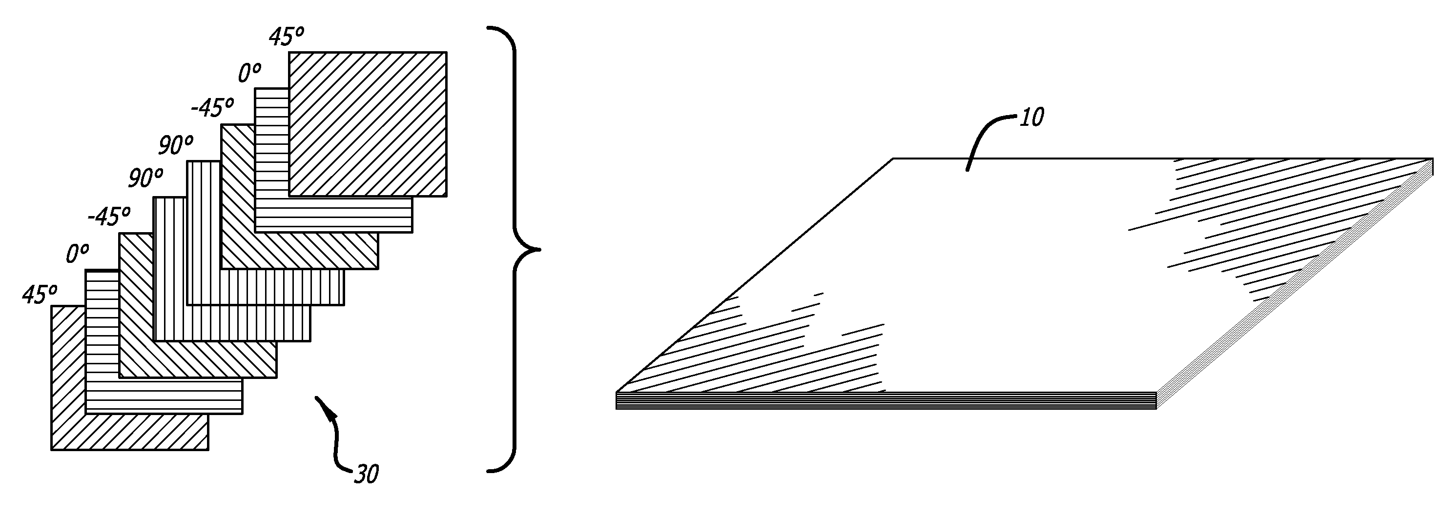
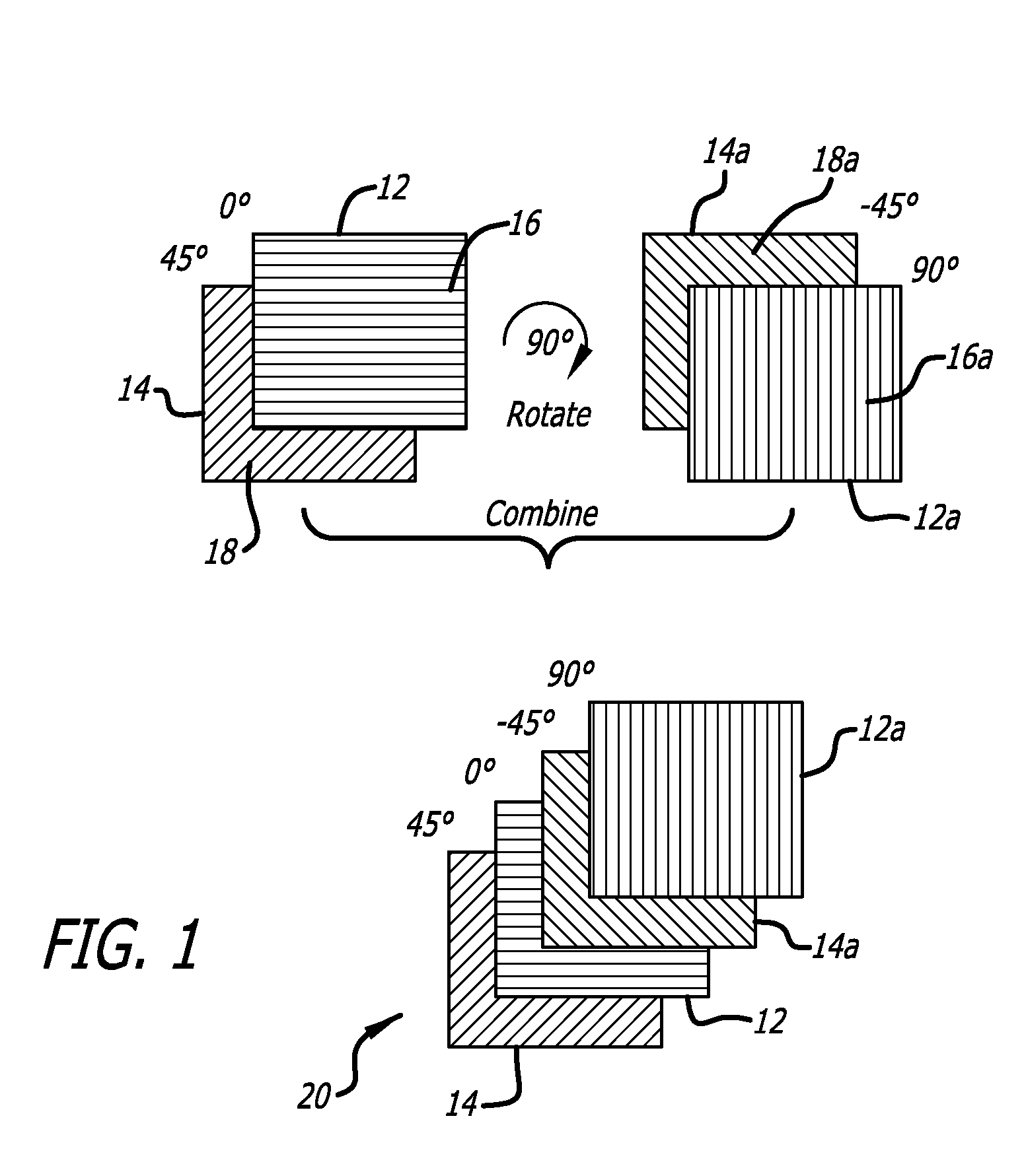
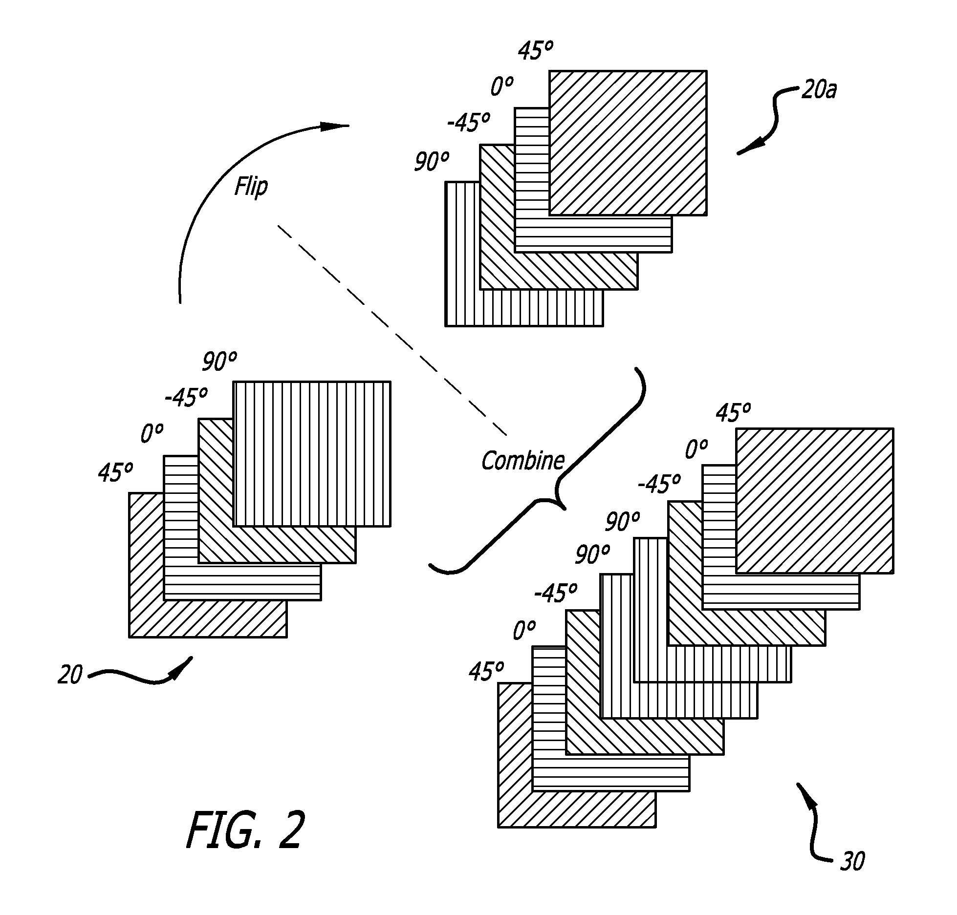
[0024]The present invention involves the formation and use of pre-plied, multi-directional laminates that are used in compression molding processes to form three dimensional parts. The invention is particularly well-suited for making three dimensional parts that have complex shapes and which are designed to carry large loads. Although the present invention finds use mainly in the aerospace industry, the process may also be used in accordance with the present invention to produce three dimensional structures that are suitable for a wide variety of applications where high strength and light weight are desired. The following detailed description is directed mainly to the production of aircraft parts as the preferred types of structures made using the present invention. It will be understood that the invention also has wide application to the production of other types of high strength parts, such as any number of complex three dimensional parts that are used in the automotive, railway, ...


PUM

PropertyMeasurementUnit
widthaaaaaaaaaa
sizeaaaaaaaaaa
thickaaaaaaaaaa

Abstract

Layers of unidirectional (UD) fiber prepreg are formed into a pre-plied, multi-directional, continuous fiber laminate that is used as a molding compound to form three dimensional structures. Cut-outs from the laminate are slotted and folded along fold lines to provide near-net-shaped preforms that may be compression molded to form fiber-reinforced composite structures having complex shapes.

Description

BACKGROUND OF THE INVENTION[0001]1. Field of the Invention[0002]The present invention relates generally to fiber-reinforced composite structures and the molding materials that are used to make such structures. More particularly, the present invention involves the use of unidirectional prepreg tape to form pre-plied, multi-directional, continuous fiber laminates that are suitable for molding complex three dimensional fiber-reinforced composite structures via near-net shaped pre-forming.[0003]2. Description of Related Art[0004]Fiber-reinforced composite structures typically include a resin matrix and fibers as the two principal components. These structures are well-suited for use in demanding environments, such as in the field of aerospace, where a combination of high strength and light weight is important.[0005]Pre-impregnated composite material (prepreg) is used widely in the manufacture of composite parts and structures. Prepreg is a combination of uncured resin matrix and fiber re...

Claims


Application Information

Patent Timeline
Patent Type & Authority Applications(United States)
IPC IPC(8): B32B5/12B29C71/02
CPCB29B11/16B29C53/04B29C70/207B29C70/345Y10T428/24124Y02T50/433Y10T428/24058Y10T156/1051B29L2031/3076Y02T50/40
Inventor KWEDER, MATTHEW
Owner HEXCEL
Why Eureka
Try Eureka