
Method & arrangement for calculating a conformity between a representation of an environment and said environment

Active Publication Date: 2011-03-17
EPIROC ROCK DRILLS AB
View PDF10 Cites 27 Cited by
  • Summary
  • Abstract
  • Description
  • Claims
  • Application Information

AI Technical Summary

Benefits of technology

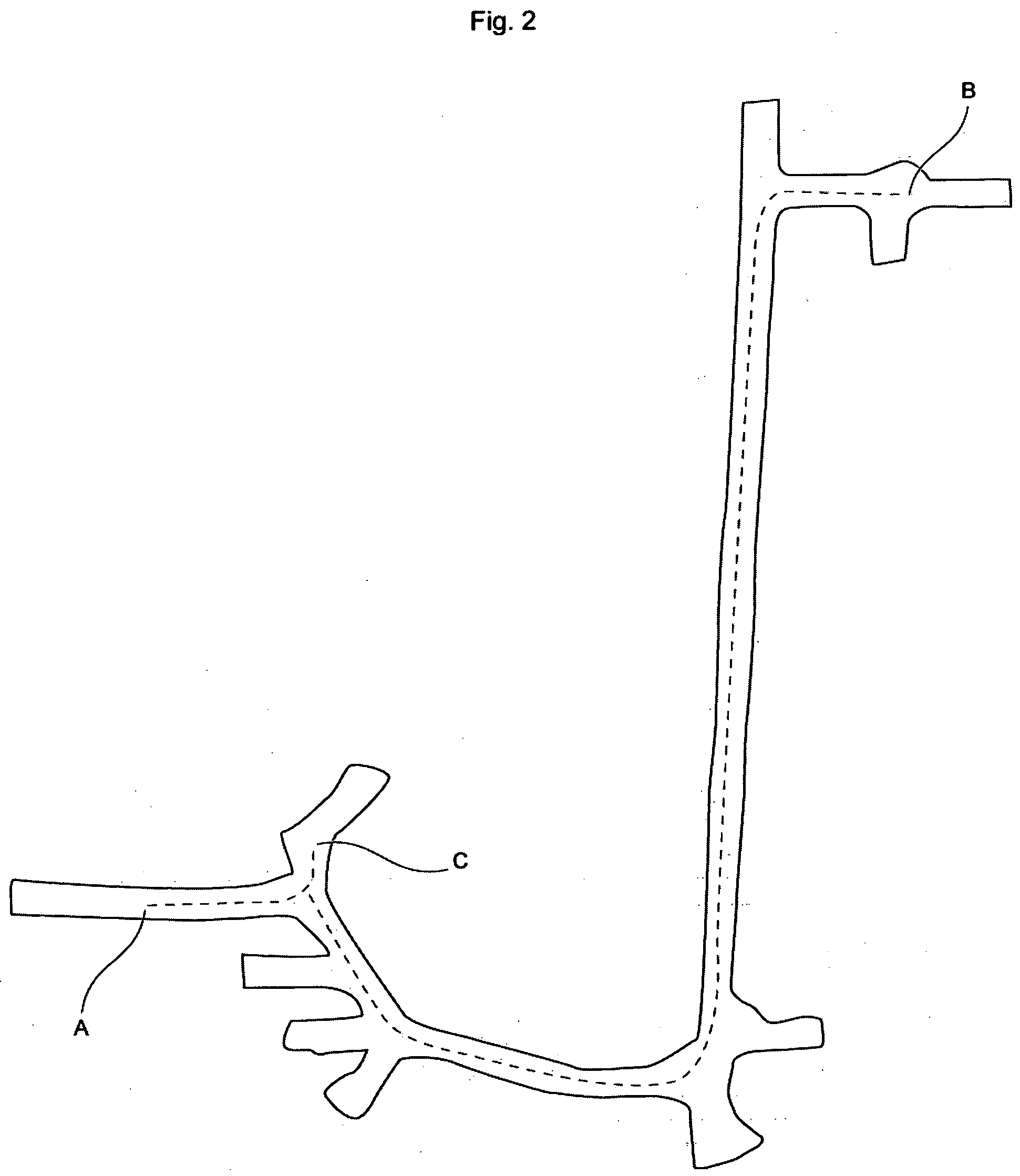
[0015]The invention has the advantage that the reliability of a representation of an environment can be determined in easy manner, e.g., by comparing distances to obstacles in different directions from a point in the representation with corresponding distances to obstacles such as walls in corresponding directions in the actual environment. If the conformity between the distance is good, one can also assume that the conformity of the representation with the reality is good. Moreover, the invention has the advantage that the verification of the maps is a fast process.

Problems solved by technology

The processes used to generate such representations of the surroundings can be complicated and much can go wrong.
The map material might be defective, e.g., because one or more of the sensors used to generate the map put out faulty signals, such as faulty distance and / or directions.
In some cases, one can even use information from a gyro measuring the machine's direction of travel, in which case a faulty gyro can put out faulty signals.
Moreover, the surroundings where the route is recorded may be such that the quality of representation of the surroundings is poor, for example, objects or surfaces may occur which absorb or reflect the light from the laser range scanners.
However, this verification is very hard to do, and normally takes a very trained eye to identify mistakes on the map, yet even then it is not certain that all deficiencies have been found.

Method used


Image

  • Method & arrangement for calculating a conformity between a representation of an environment and said environment
  • Method & arrangement for calculating a conformity between a representation of an environment and said environment
  • Method & arrangement for calculating a conformity between a representation of an environment and said environment

Examples


Embodiment Construction

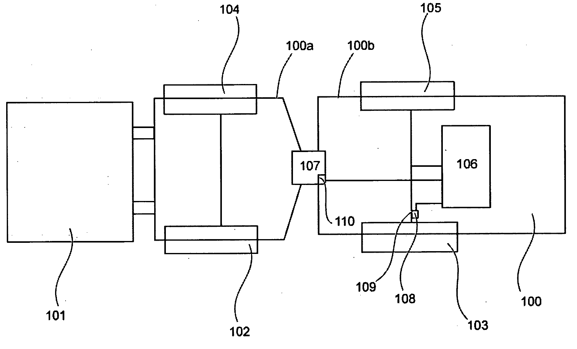
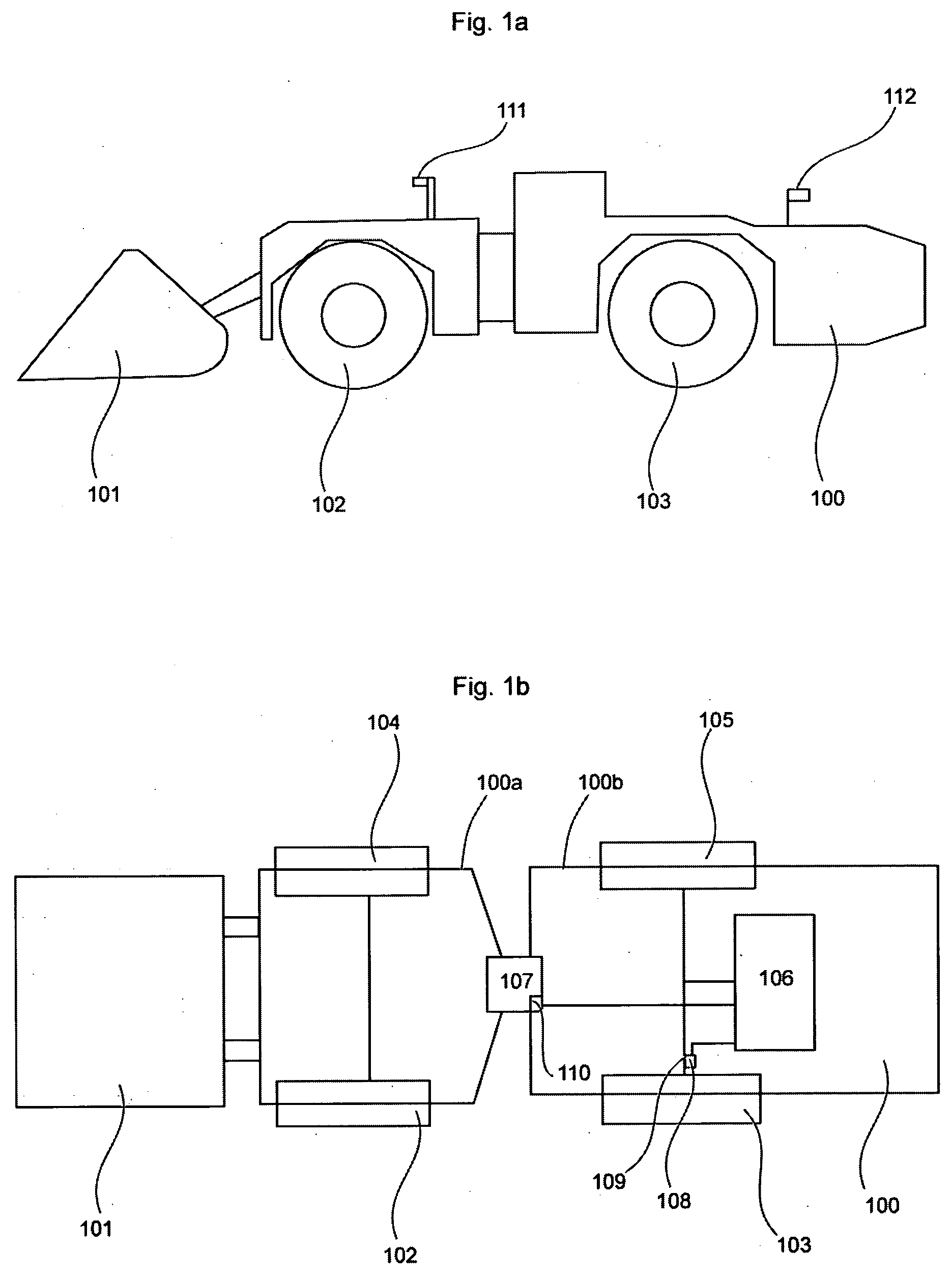
[0023]FIG. 1 A, B, shows a vehicle 100 from the side and top, respectively. The vehicle 100 is part of a loading machine in which present invention can be used to advantage. The machine 100 comprises a bucket 101 and wheels 102-105, and a control unit 106, which controls various functions of the machine 100. As shown in FIG. 1b, the machine is part of an articulated vehicle, whose front section 100a is joined to a rear section 100b via a joint 107. The machine also comprises at least one wheel rotation sensor 108, such as an odometer, which can be arranged on the axle emerging from the transmission and puts out signals representing the drive wheel's rotation and / or distance travelled. In an alternative embodiment, one can use a sensor arranged on the machine's drive axle 109, which puts out signals representing the rotation of the drive axle 109 and, thus, the drive wheel. The sensor 108 puts out signals to the control unit 106. Moreover, arranged at the joint 107 is a joint angle s...


PUM


Abstract

The present invention concerns a method for determining a conformity between a representation of an environment and said environment, wherein said representation of the environment constitutes a representation in at least two dimensions, where a distance between two points in the representation has a known relation to the corresponding distance in said environment, characterised in that said determination involves the step of determining a first set of parameter values for a first position in said representation of the environment, comparing said first determined set of expected parameter values with a second set of parameter values, where said second set of parameter values has been determined for a second position, where said second position constitutes a position in said environment that essentially corresponds to said first position, and using said comparison to determine a measure of conformity between said environment and said representation of the environment. The invention also concerns an arrangement and the mining and / or construction machine.

Description

TECHNICAL FIELD[0001]The present invention concerns verification of a representation of an environment, and a method to verify a representation of an environment. The invention also deals with an arrangement and a mining and / or construction machine.PRIOR ART[0002]In many fields there is a constant process of improving the efficiency, productivity and safety, one of which is underground mining. One area in such mining where changes / improvements are taking place to accomplish the above involves automating certain functions for at least some of the vehicles / machines used in the mine. For example, it is desirable that certain machines, such as loading machines, be automatically driven, that is, not only can the machine be driven without a driver, but it can also perform functions totally by itself.[0003]On example of such vehicles where automated operation is desired consists of so-called LHD (loading, hauling and dumping) machines. These machines are often used to remove broken rock, h...

Claims


Application Information

Patent Timeline
IPC IPC(8): G06F19/00B60W60/00G01S17/89G05D1/02
CPCG09B29/005G01C21/30G01C7/06G01C15/002G01S17/89E21F13/02G05D1/43G05D1/246
Inventor LARSSON, JOHANKRASSER, MICHAEL
Owner EPIROC ROCK DRILLS AB
Learn More