
Rotary one-dimensional barcode reading device

Inactive Publication Date: 2011-03-24
HOULY
View PDF2 Cites 7 Cited by
  • Summary
  • Abstract
  • Description
  • Claims
  • Application Information

AI Technical Summary

Benefits of technology

[0009]In the rotary one-dimensional barcode reading device described above, an additional light source is provided to generate a light spot for aligning to a center of a barcode to be read so as to facilitate the reading of the barcode. The light spot will be off when the LED light source is on for eliminating interference.
[0010]In the rotary one-dimensional barcode reading device described above, the motor and the light source of the barcode reader can be arranged to power on at the same time or in an independent manner wherein due to the time period desired to completely actuate the motor, the motor can be kept in a condition of continuous rotation at a constant speed so as to improve the reading efficiency of barcodes. Alternatively, the light source can be arranged to power on only when a barcode is approaching.

Problems solved by technology

The alignment is time-consuming and elaborate operation.
(1) A laser is used as a light source. A polygonal mirror is rotated to re-direct and project a plurality of laser beams in various directions. At least one of the laser beams may get oriented substantially normal to the barcode to be read regardless the direction in which the barcode is positioned. Reading of the barcode can thus be done correctly. However, the mechanical arrangement is complicated and elaborate, making it very expensive.
(2) LEDs are used as light sources. Photographing means is taken to picture the whole barcode, which is received by a rectangular array of CCD or CMOS sensors to convert to an electronic signal. Numerous electronic signals are then analyzed to obtain the desired 1-D barcode signal. An example is shown in U.S. Pat. No. 7,428,991. The disadvantage is that a large number of light sources is needed in order to cover the whole area of the barcode. The CCD / CMOS sensor array is much more expensive than a linear CCD / CMOS sensor. Increasing the number of pixels makes the amount of signals to be analyzed increased and the decoder used must be upgraded or faster. All lead to high costs.

Method used


Image

  • Rotary one-dimensional barcode reading device
  • Rotary one-dimensional barcode reading device
  • Rotary one-dimensional barcode reading device

Examples


first embodiment

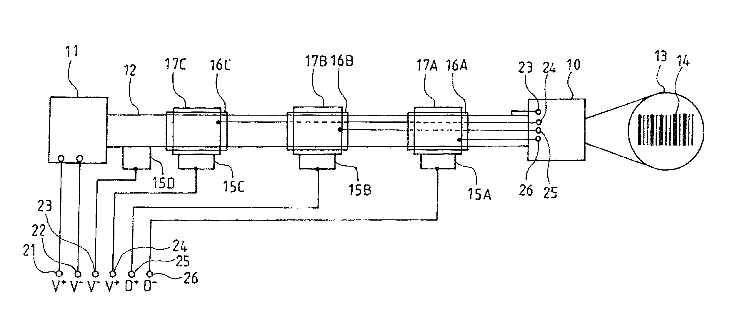
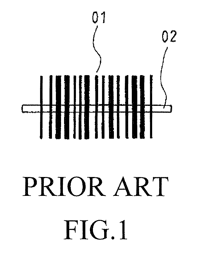
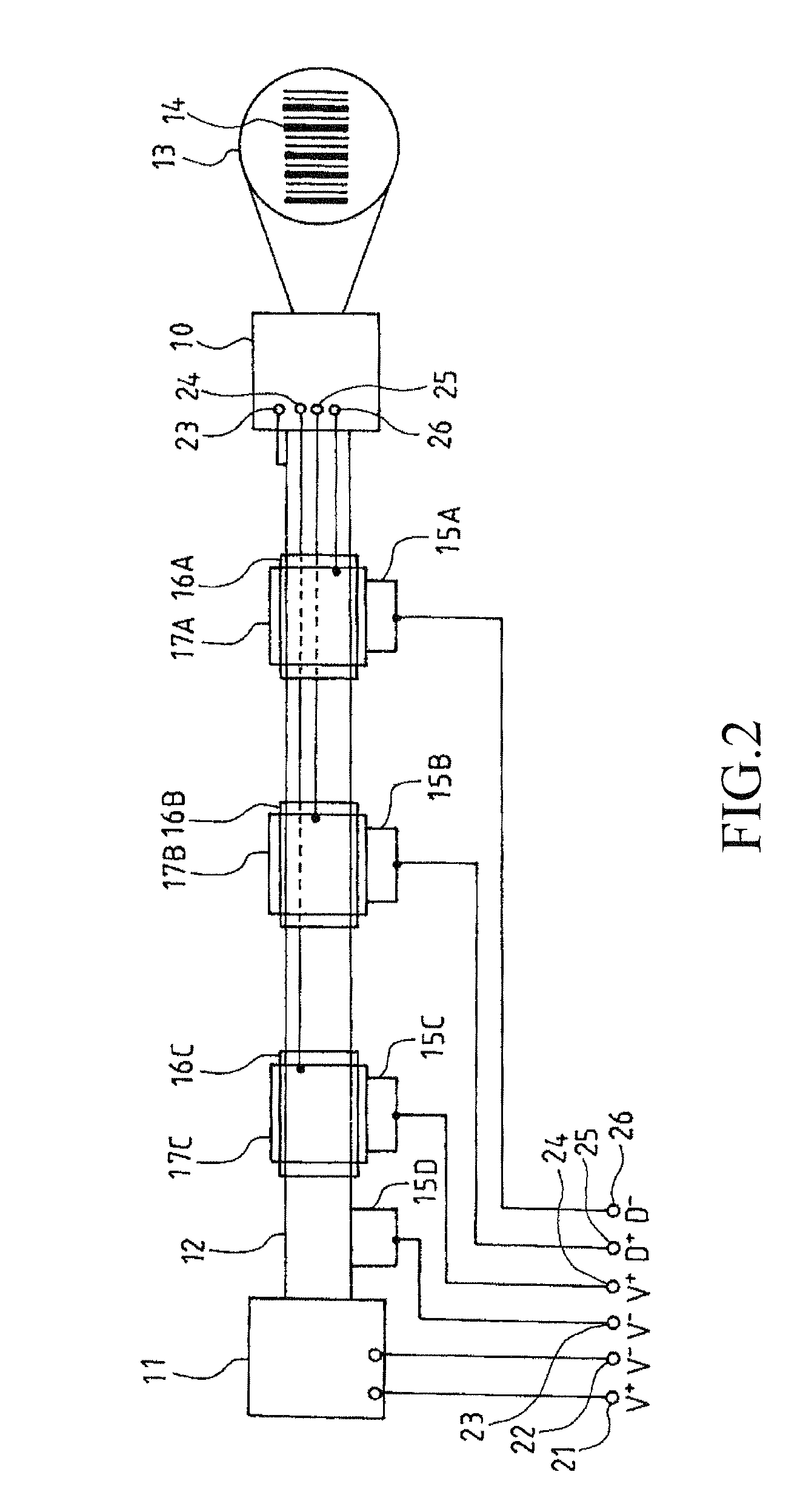
[0021]Referring to FIG. 2, the present invention is shown. The present invention is constructed to comprise an existing direction-dependent 1-D barcode reader 10, which is known in the art, having a light source 02 that is linear and the same as that shown in FIG. 1. The linear light source 02 must be manipulated in a manual manner to align to the direction normal to a barcode 01 in order to read the barcode 01. The present invention mainly comprises a motor 11 and the shaft 12 mounted to the motor 11. The barcode reader 10 is mounted to the shaft 12, whereby when the motor 11 is put into rotation, the light source of the barcode reader 10 is converted from a linear form into a circular light irradiation surface 13 as shown in the drawing. The light irradiation surface 13 is sized to completely cover the barcode 14. Consequently, regardless of the direction in which the barcode 14 is positioned, the barcode 14 can be properly read. The light source used can be visible or invisible.

[...

second embodiment

[0023]Referring to FIG. 3, in the present invention, a direct-current (DC) motor is adopted. The DC motor may share the same power source with the barcode reader 10 and the wiring arrangement is illustrated in the drawing.

third embodiment

[0024]Referring to FIG. 4, in the present invention, the shaft 12 is made hollow and the power line 24 extends through an aperture 27 into the hollow interior of the shaft 12. Similarly, the signal line 25 extends from the inside to the outside of the shaft 12 through an aperture 28. In this way, the insulation rings 16A, 16B can be past around. The manufacturing of the this arrangement may combine the insulation rings 16A, 16B, 16C together as a unitary member. Or alternatively, a shaft made of insulation substance may be used and in this case, the insulation rings 16A, 16B, 16C can be omitted. The metal rings 17A, 17B, 17C can be mounted by adhesives or can alternatively fixed in the manner shown in the drawing with pins 18A, 18B, 18C.

[0025]Referring to FIG. 4, the present invention may further comprises a laser light source that project a laser beam to a center of a barcode to be read as a pointing light spot 19 to facilitate reading. It will be switched off when the LED light so...


PUM


Abstract

A rotary one-dimensional barcode reading device includes a motor and a one-dimensional barcode reader attached to the motor shaft so as to allow the reader to rotate with the motor shaft, by which linearity of the light source and the receiver of the barcode reader are converted into circularity to realize direction-diversified linear light sources and receives in various directions. Input and output of power source and signals are performed through electrical brushes. With this arrangement, a one-dimensional barcode in any direction can be properly read and the electronic signal generated by the one-dimensional barcode so read is transmitted through the electrical brushes or in a wireless manner to a computer, a point-of-sale (POS), a personal digital assistant (PDA), and the likes.

Description

(a) TECHNICAL FIELD OF THE INVENTION[0001]The present invention generally relates to a rotary one-dimensional (1-D) barcode reading device, and more particularly to a direction-independent 1-D barcode reading device, which is realized by rotating an existing direction-dependent 1-D barcode reader with a motor.(b) DESCRIPTION OF THE PRIOR ART[0002]One-dimensional (1-D) barcodes have been in existence for more than half a century. The general idea of the 1-D barcode reading is to irradiate a light source to a barcode and then receive the light reflected by the barcode, followed by converting the received reflection light into electronic signal. The electronic signal is then decoded by a decoder to determine the commodity associated therewith. The light source used include for example light-emitting diode (LED) and laser diode and the receiver for the reflection light include for example a charge-coupled device (CCD), a complementary metal-oxide semiconductor (CMOS) device, and a photo...

Claims


Application Information

Patent Timeline
IPC IPC(8): G06K7/10
CPCG06K7/1456G06K7/10544
Inventor LIU, KUO-SHEN
Owner HOULY
Learn More