Methods and apparatus for ceiling mounted systems

a ceiling mounted and ceiling technology, applied in lighting and heating equipment, instruments, lighting support devices, etc., can solve the problems of mercury pollution, increased use of these technologies, and significant material and maintenance costs, and achieve the effect of generating additional cost for fluorescent lights, reducing the cost of replacement, and increasing the cost of material and maintenan

Active Publication Date: 2011-03-24
LIGHTING DEFENSE GRP LLC
View PDF13 Cites 15 Cited by
  • Summary
  • Abstract
  • Description
  • Claims
  • Application Information

AI Technical Summary

Benefits of technology

[0035]The modular system facilitates consolidation of multiple devices on a single platform, which tends to save time and cost of installation and operation. System integration on a single ceiling suspended platform is functional, economical, and architecturally pleasing. The modular platform may provide a power and communication wire way that at least partially integrates lighting, sound, security, fire protection, surveillance, data, and communication and environmental control devices on one platform.
[0036]In addition, the modular system may optimize system efficiency for all devices, enhance functionality by enabling system cross-communication, enhance interior operational environment through better illumination, sound quality, noise control, security and safety device integration, air quality control, etc. The modular system may offer ease of design, reconfiguration, and maintenance, and reduce cost of ownership, construction, operation, and maintenance. Further benefits may include reducing construction costs through limiting the number of trades on the job, accelerating construction progress, and reducing installation errors; reducing energy and resource usage through integrating multiple devices in one platform; reducing manufacturing, shipping and transportation costs by scaling down the product and cutting energy costs by deploying lighting and other capabilities in an efficient manner; reducing maintenance costs through using long-life self-reporting devices which enable smart servicing schedules; and offering through a single point of contact engineering assessment, system design consulting, product procurement, shipping logistics, system commissioning, technical support and long term customer care.

Problems solved by technology

However, the use of these technologies is increasingly counterproductive due to limitations such as energy inefficiency, high front end cost, maintenance costs, poor light quality, and negative environmental impact.
Commercial office space frequently utilizes fluorescent technology, which requires significant expenditures for the costs of material, maintenance, and energy consumption.
Typically, fluorescent technology includes large and heavy structures, which require additional secondary support mechanisms for their installation.
Replacement of fluorescent lights also generates additional cost due to mercury and other materials within the lamp.
Consequently, fluorescent lights often must be disposed of as hazardous waste.
Fluorescent technology generally consumes high levels of energy and is a significant source of costs in operating a commercial office building.
A portion of the energy consumed by fluorescent lamps is dissipated as heat, thus increasing the building's mechanical load.
Costs associated with removal of the heat generated by fluorescent lamps include initial front end cost, such as upsizing the HVAC units, subsequent operational costs resulting from higher energy consumption, and increased maintenance costs.
Although improvements in fluorescent technology such as the development of lower wattage lamps with improved electrodes and coatings as well as more efficient electronic ballasts have reduced, but not eliminated, the amount of heat dissipated by such systems, these improvements have not solved problems with visual comfort and energy inefficiency.
However, fluorescent lamps with series wired ballasts cannot function with fewer lamps than intended, making delamping infeasible which requires additional expenditures for retrofitting.
While such indirect lighting fixtures are generally pleasant, the design of the indirect fluorescent luminaires optics often does not account for the ceiling reflective properties, thus delivering reduced light levels at the work surface.

Method used


Image

  • Methods and apparatus for ceiling mounted systems
  • Methods and apparatus for ceiling mounted systems
  • Methods and apparatus for ceiling mounted systems

Examples


Embodiment Construction

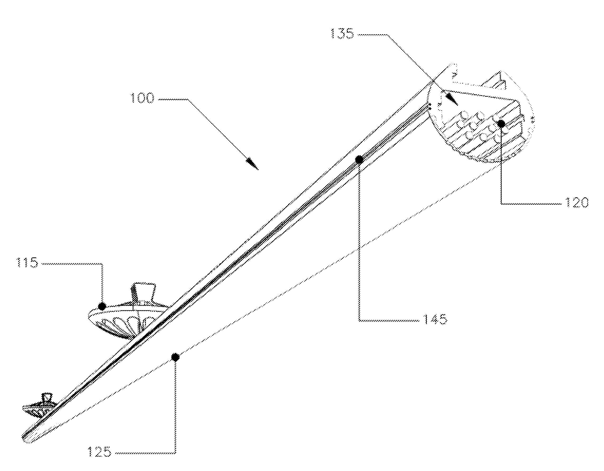
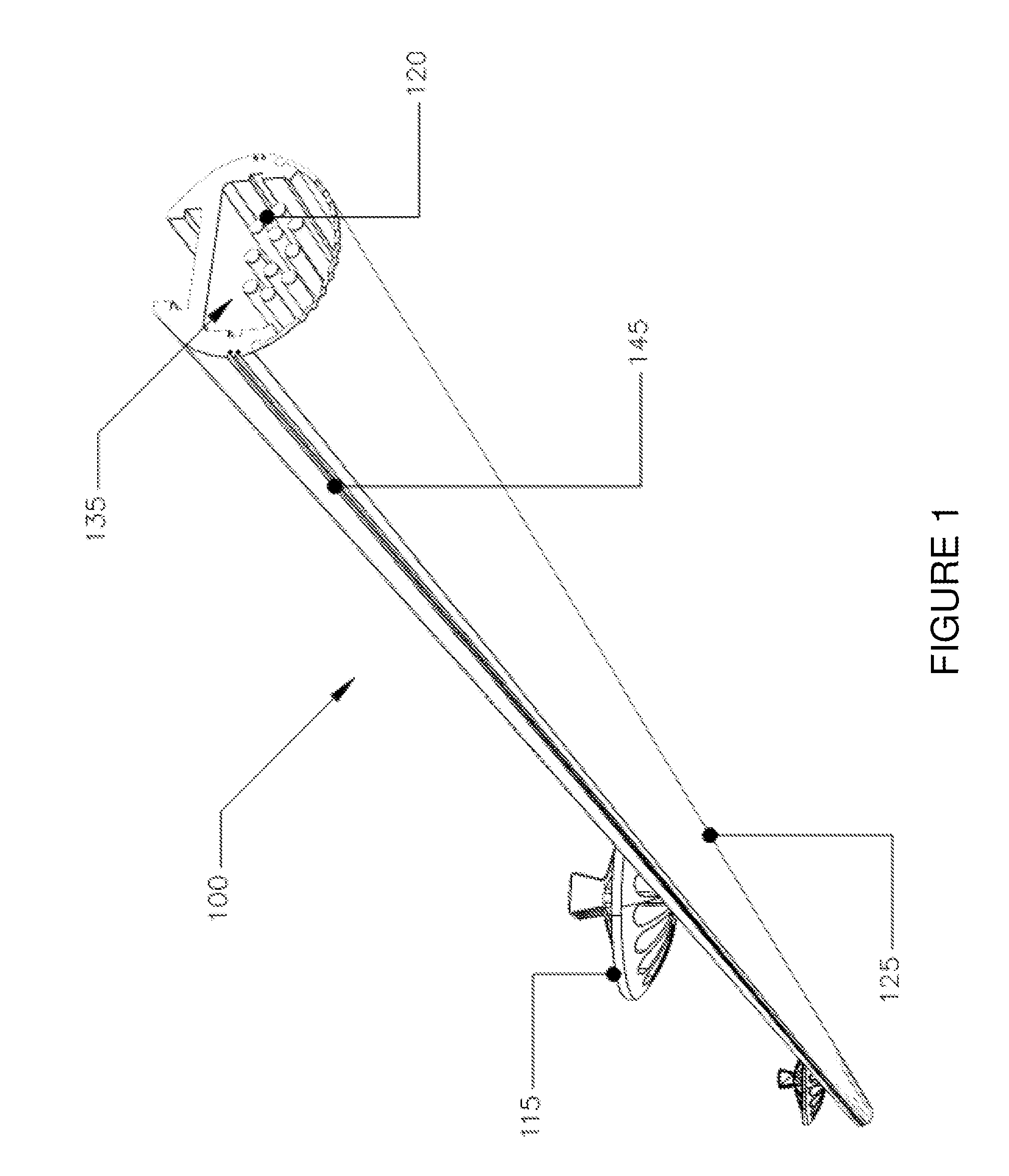
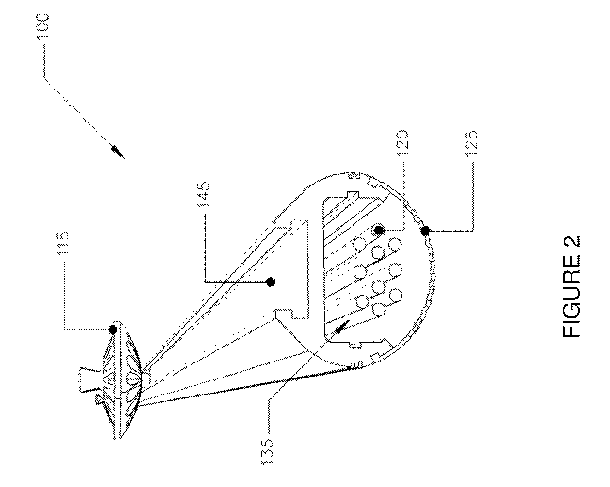
[0032]The present invention may be described in terms of functional block components and various processing steps. Such functional blocks may be realized by any number of components configured to perform the specified functions and achieve the various results. For example, the present invention may employ various process steps, apparatus, systems, methods, etc. In addition, the present invention may be practiced in conjunction with any number of systems and methods for providing ceiling suspended systems, and the system described is merely one exemplary application for the invention. Further, the present invention may employ any number of conventional techniques for installing, controlling, enhancing, retrofitting, monitoring, updating, and / or replacing ceiling suspended systems.

[0033]The particular implementations shown and described are illustrative of the invention and its best mode and are not intended to otherwise limit the scope of the present invention in any way. For the sak...


PUM


Abstract

Methods and apparatus for ceiling suspended systems according to various aspects of the present invention include a modular platform for supporting and supplying multiple devices. A wire way bar may facilitate connection and support for the devices, such as light sources and other systems.

Description

CROSS-REFERENCES TO RELATED APPLICATIONS[0001]This application claims the benefit of U.S. Provisional Patent Application No. 61 / 241,484, filed Sep. 11, 2009, U.S. Provisional Patent Application No. 61 / 295,264, filed Jan. 15, 2010, and U.S. Provisional Patent Application No. 61 / 301,846, filed Feb. 5, 2010, and incorporates the disclosure of each application by reference.BACKGROUND OF THE INVENTION[0002]Most indoor commercial spaces, such as offices, use incandescent, halogen, or fluorescent technology to provide light. These technologies can be used to illuminate many types of areas including employee workspaces, common use areas, and parking garages. However, the use of these technologies is increasingly counterproductive due to limitations such as energy inefficiency, high front end cost, maintenance costs, poor light quality, and negative environmental impact.[0003]Commercial office space frequently utilizes fluorescent technology, which requires significant expenditures for the c...

Claims


Application Information

Patent Timeline
Patent Type & Authority Applications(United States)
IPC IPC(8): H05B37/02F21V21/00F21V29/00F21V7/00
CPCF21S2/00F21S2/005F21V5/04F21V7/0008F21V13/04F21V29/74F21V23/0442F21V27/00F21V29/02F21V33/0076F21Y2101/02F21V23/04F21Y2115/10F21V29/67
Inventor SPIRO, DANIEL S.WHITNEY, LELAND R.
Owner LIGHTING DEFENSE GRP LLC
Why Eureka
Try Eureka