Image forming apparatus

a technology of image forming apparatus and exposure head, which is applied in the direction of electrographic process apparatus, printing, instruments, etc., can solve the problems of optical system blur and inability to form latent images, and achieve the effect of improving the positioning accuracy of the exposure head with respect to the image carrier

Inactive Publication Date: 2011-03-24
SEIKO EPSON CORP
View PDF4 Cites 7 Cited by
  • Summary
  • Abstract
  • Description
  • Claims
  • Application Information

AI Technical Summary

Benefits of technology

[0020]The support member may be configured to include a holding member that holds the exposure head and a contact member that is provided to the holding member and is in contact with the image carrier. By connecting the contact member coming into contact with the image carrier and the exposure head via the holding member in the manner described above, positioning accuracy of the exposure head with respect to the image carrier can be improved.

Problems solved by technology

Because, if the distance is too large, the spot formed on the image carrier by the optical system blurs and a good latent image may not be formed.

Method used


Image

  • Image forming apparatus
  • Image forming apparatus
  • Image forming apparatus

Examples


Embodiment Construction

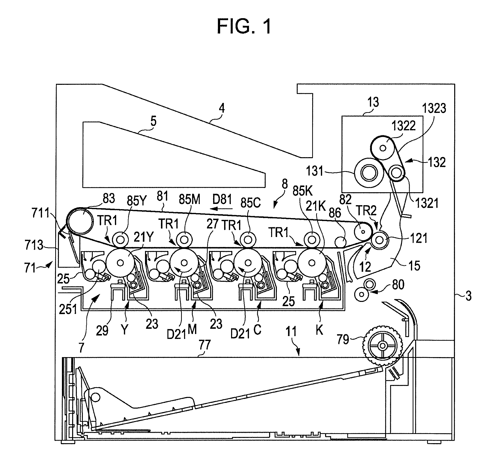
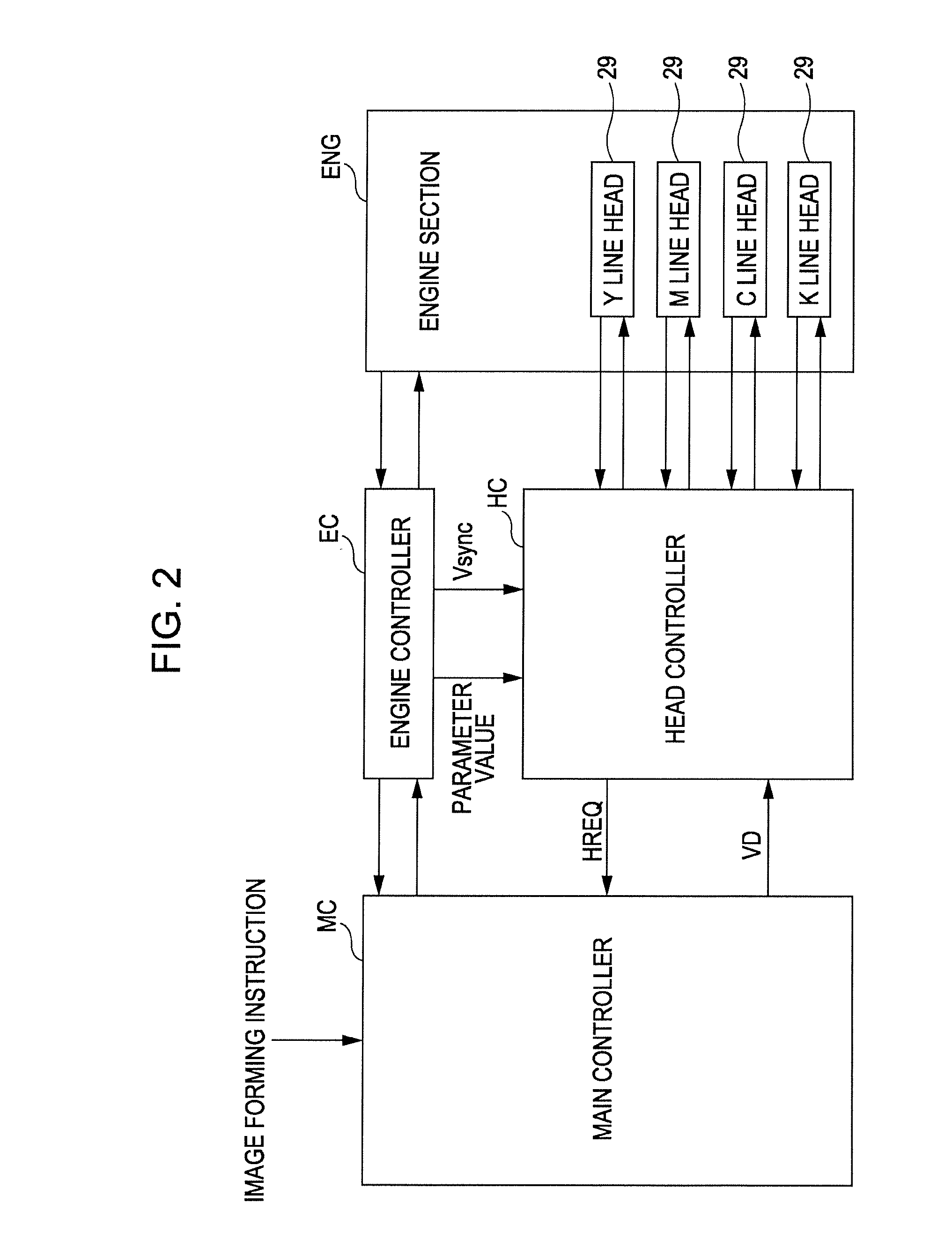
[0032]FIG. 1 is a diagram showing an example of an image forming apparatus to which the invention can be applied. FIG. 2 is a block diagram showing an electrical configuration of the image forming apparatus of FIG. 1. The image forming apparatus selectively performs a color mode in which a color image is formed by superimposing four color toners of black (K), cyan (C), magenta (M), and yellow (Y), and a monochrome color mode in which a monochrome image is formed by only black toner (K). FIG. 1 is a diagram when performing the color mode. In the image forming apparatus, when an image forming instruction is provided from an external apparatus such as a host computer to a main controller MC including a CPU, a memory, and the like, the main controller MC provides a control signal or the like to an engine controller EC and provides video data VD corresponding to the image forming instruction to a head controller HC. In this case, every time the main controller MC receives a horizontal re...


PUM


Abstract

An image forming apparatus includes: an exposure head that includes a light emitting device for emitting light having a first wavelength and a second wavelength and an optical system having a first lens surface through which the light emitted from the light emitting device enters and a second lens surface from which the light entered through the first lens surface is emitted, forms an image of the light having the first wavelength at a first image forming position, and forms an image of the light having the second wavelength at a second image forming position different from the first image forming position in an optical axis direction of the optical system; a latent image carrier onto which the light emitted from the second lens surface of the exposure head is irradiated and a latent image is formed; and a support member that supports the exposure head.
The support member supports the exposure head so that the exposure head and the latent image carrier have the following relationship:
d1<di<d2
here, d1, di, and d2 are defined as follows:
d1: a distance between the second lens surface and the first image forming position in the optical axis direction,
d2: a distance between the second lens surface and the second image forming position in the optical axis direction, and
di: a distance between the second lens surface and the image carrier in the optical axis direction.

Description

BACKGROUND[0001]1. Technical Field[0002]The present invention relates to an image forming apparatus that exposes an image carrier by using an exposure head that forms an image of light from a light emitting device by an optical system.[0003]2. Related Art[0004]In an image forming apparatus described in JP-A-2008-221790, an exposure head (line head in JP-A-2008-221790) including a light emitting device and an image forming optical system is arranged to face an image carrier, and when the image forming optical system forms an image of light from the light emitting device, a spot is formed on (a surface of) the image carrier. The exposure head appropriately forms spots at positions corresponding to image data, so that a predetermined latent image can be formed on the surface of the image carrier.[0005]In an image forming apparatus as described above, a distance between the image forming position of the light of the optical system and the image carrier is important. Because, if the dist...

Claims


Application Information

Patent Timeline
Patent Type & Authority Applications(United States)
IPC IPC(8): B41J2/435
CPCB41J2/45B41J2/451G03G15/04045G03G2221/1636G03G21/1666G03G15/326
Inventor SOWA, TAKESHIIKUMA, KEN
Owner SEIKO EPSON CORP
Why Eureka
Try Eureka