Backlight module and liquid crystal display apparatus

a liquid crystal display and backlight module technology, applied in lighting and heating apparatus, instruments, diffusing elements, etc., can solve the problems of increasing obstructing fabrication, and limited light emitting angle range of the surface light source, so as to facilitate the assembly reduce the cost of the backlight module , the optical efficiency of the backlight module is increased, the effect of facilitating the assembly

Inactive Publication Date: 2011-03-24
CORETRONIC
View PDF8 Cites 11 Cited by
  • Summary
  • Abstract
  • Description
  • Claims
  • Application Information

AI Technical Summary

Benefits of technology

[0010]The invention is directed to a backlight module, wherein the assembly of the backlight module is facilitated, the cost of the backlight module is decreased, and the optical efficiency of the backlight module is increased.
[0011]The invention is directed to a liquid crystal display apparatus, wherein the assembly of the liquid crystal display apparatus is facilitated, the cost of the liquid crystal display apparatus is decreased, and the optical efficiency of the liquid crystal display apparatus is increased, and the liquid crystal display apparatus uses the ambient light efficiently.
[0015]In the embodiments of the invention, the lenses are located between the reflective layer and the lighting unit, and the diffusion layer is located at one side of the reflective layer facing away from the lighting unit. Thereby, the illumination beam emitted by the back light unit is converged by the lens, and then the illumination beam is diffused by the diffusion layer, so that the backlight module may provide a uniform surface light source, and then the LCD panel may provide a high quality frame. In addition, a light emitting angle of the reflected ambient light is increased, which is useful that the reflected ambient light served as another good back light source of the liquid crystal panel due to the ambient light being diffused twice by the diffusion layer before and after being reflected by the reflective layer.

Problems solved by technology

In addition, in order to increase a brightness of the frames, a light emitting angle range of the surface light source is limited to avoid light loss.
However, such a method that four optical films are disposed in the light guide plate increases the cost of the backlight module, and too many optical films also obstruct fabrication and it is hard to decrease a thickness of the backlight module.
If the transmissive LCD is used in an outdoor environment, an ambient light is too strong to identify the frames displayed by the transmissive LCD.
However, when a strong light strikes a surface of the reflective LCD, the reflective light is also too strong to identify the frames.
Presently, although a transflective type LCD is developed to adapt to the indoor environment and the outdoor environment, the problem that the users may not easily see the frames caused by the strong ambient light and the strong reflective light is not over come.

Method used


Image

  • Backlight module and liquid crystal display apparatus
  • Backlight module and liquid crystal display apparatus
  • Backlight module and liquid crystal display apparatus

Examples


Embodiment Construction

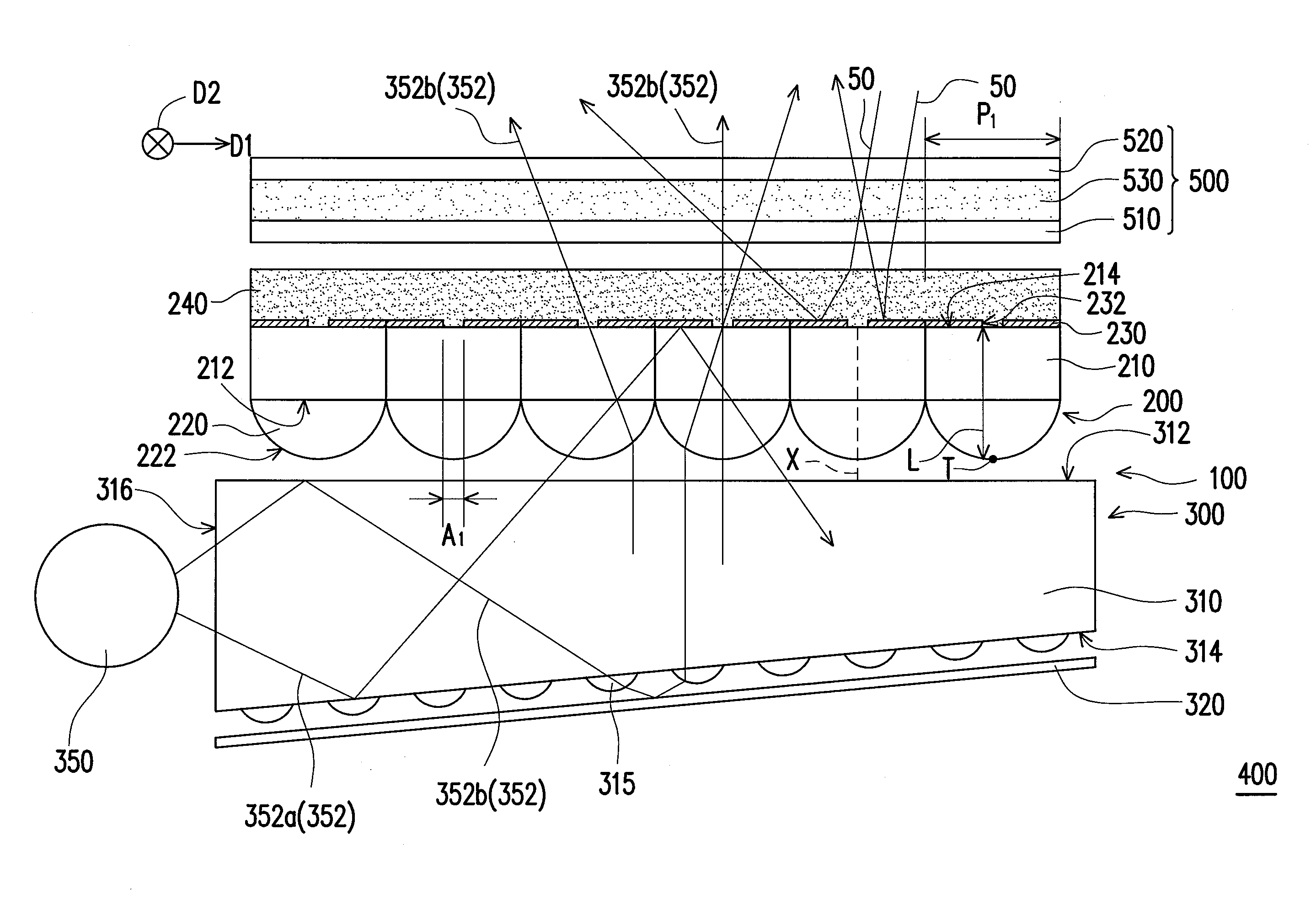
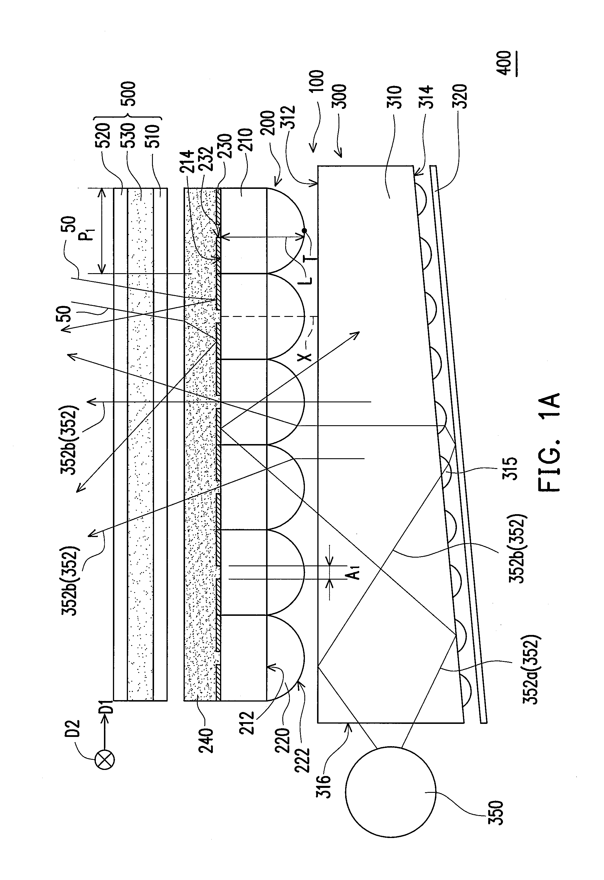
sheet shown in FIG. 1A.

[0021]FIG. 3A is a bottom view of a brightness enhancement sheet according to another embodiment of the invention.

[0022]FIG. 3B is a bottom view of the brightness enhancement sheet according to another embodiment of the invention.

[0023]FIG. 4 is a cross-sectional diagram of a backlight module according to another embodiment of the invention.

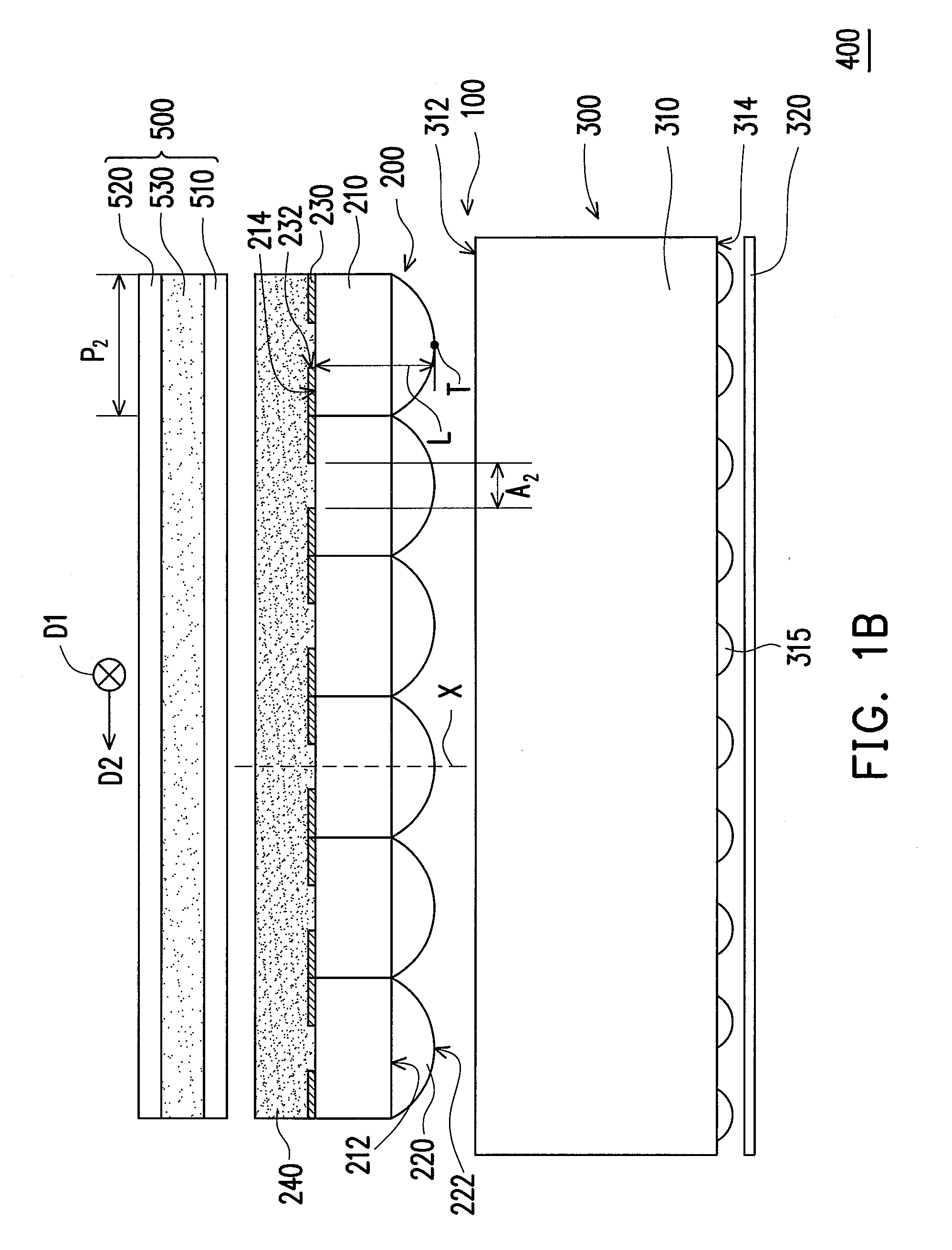
[0024]FIG. 5 is a cross-sectional diagram of a backlight module according to another embodiment of the invention.

DESCRIPTION OF THE EXEMPLARY EMBODIMENTS

[0025]In the following detailed description of the preferred embodiments, reference is made to the accompanying drawings which form a part hereof, and in which are shown by way of illustration specific embodiments in which the invention may be practiced. In this regard, directional terminology, such as “top,”“bottom,”“front,”“back,” etc., is used with reference to the orientation of the Figure(s) being described. The components of the invention can be positioned in a number...


PUM

PropertyMeasurementUnit
brightnessaaaaaaaaaa
curvature radiusaaaaaaaaaa
refractive indexaaaaaaaaaa

Abstract

A backlight module includes a lighting unit and a brightness enhancement sheet. The brightness enhancement sheet is disposed beside the lighting unit. The brightness enhancement sheet includes a light-transmissive substrate, a plurality of lenses, a reflective layer, and a diffusion layer. The light-transmissive substrate has a first surface and a second surface opposite to the first surface. The first surface is located between the second surface and the lighting unit. The lenses are disposed on the first surface. The reflective layer is disposed on the second surface. The reflective layer has a plurality of light-transmissive openings respectively located on the optical axes of the lenses. The diffusion layer is disposed on the reflective layer and covers the light-transmissive openings. The reflective layer is disposed between the diffusion layer and the second surface. A liquid crystal display apparatus is also provided.

Description

CROSS-REFERENCE TO RELATED APPLICATION[0001]This application claims the priority benefit of Taiwan application serial no. 98131782, filed on Sep. 21, 2009. The entirety of the above-mentioned patent application is hereby incorporated by reference herein and made a part of this specification.BACKGROUND OF THE INVENTION[0002]1. Field of the Invention[0003]The invention relates to a display apparatus and a light source, and more particularly, to a liquid crystal display apparatus and a backlight module.[0004]2. Description of Related Art[0005]With the advancement of technology, a flat display becomes a mainstream of the display device to replace a conventional cathode ray tube (CRT) having a big volume and heavy weight. In flat displays, liquid crystal display (LCD) is popular with people. The LCD includes a liquid crystal panel and a backlight module but is unable to emit light spontaneously. The liquid crystal panel is used to determine a light transmittance. Thereby, the backlight m...

Claims


Application Information

Patent Timeline
Patent Type & Authority Applications(United States)
IPC IPC(8): G02F1/1335F21V7/04
CPCG02B6/0036G02F2001/133607G02F1/133605G02B6/0053G02F1/133607
Inventor SHIAU, TZENG-KEWENG, CHAO-HUNGLI, CHING-SHIANG
Owner CORETRONIC
Why Eureka
Try Eureka