Cutting Insert with Protrusions Formed at Corner Area Thereof

a cutting insert and protruding technology, applied in the field of cutting inserts, can solve the problems of workpiece damage, serrated cutting inserts, and workpieces that may be damaged, and achieve the effect of low cutting for

Inactive Publication Date: 2011-03-24
TAEGUTEC
View PDF10 Cites 26 Cited by
  • Summary
  • Abstract
  • Description
  • Claims
  • Application Information

AI Technical Summary

Benefits of technology

The cutting insert according to the present invention having the structure and function as described above can control the chip under the conditions of a low cut depth and a high cut depth and can machine the work-piece with a low cutting force.

Problems solved by technology

Consequently, the work-piece and the tool may be damaged by the chips.
In particular, to machine mild steel generating chips which are difficult to control (that is, not bent easily), the serrated cutting insert is required.

Method used


Image

  • Cutting Insert with Protrusions Formed at Corner Area Thereof
  • Cutting Insert with Protrusions Formed at Corner Area Thereof
  • Cutting Insert with Protrusions Formed at Corner Area Thereof

Examples


Embodiment Construction

Hereinafter, the present invention is described in detail with reference with the accompanying drawings.

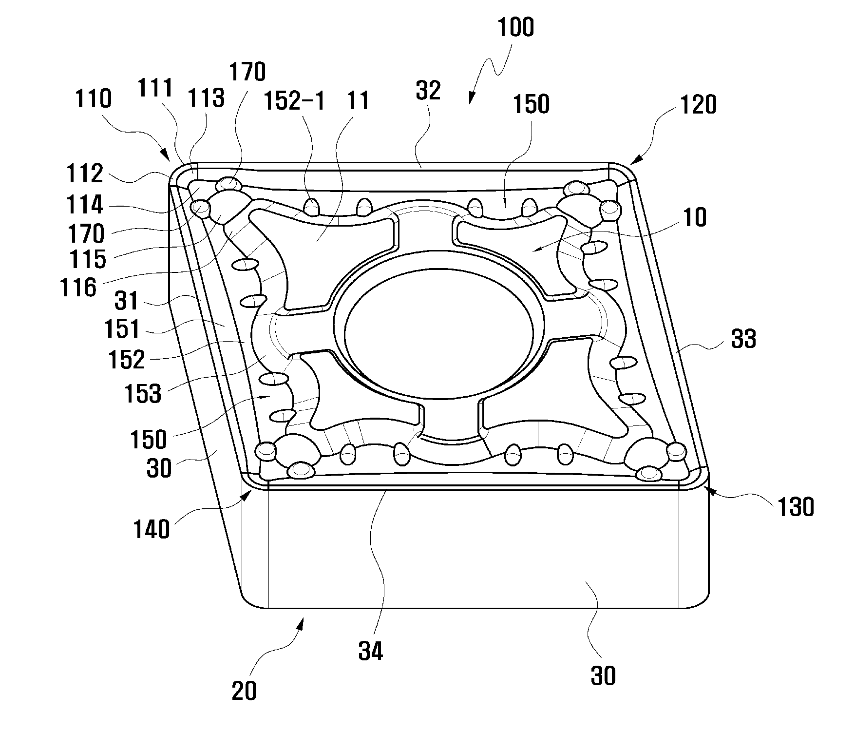
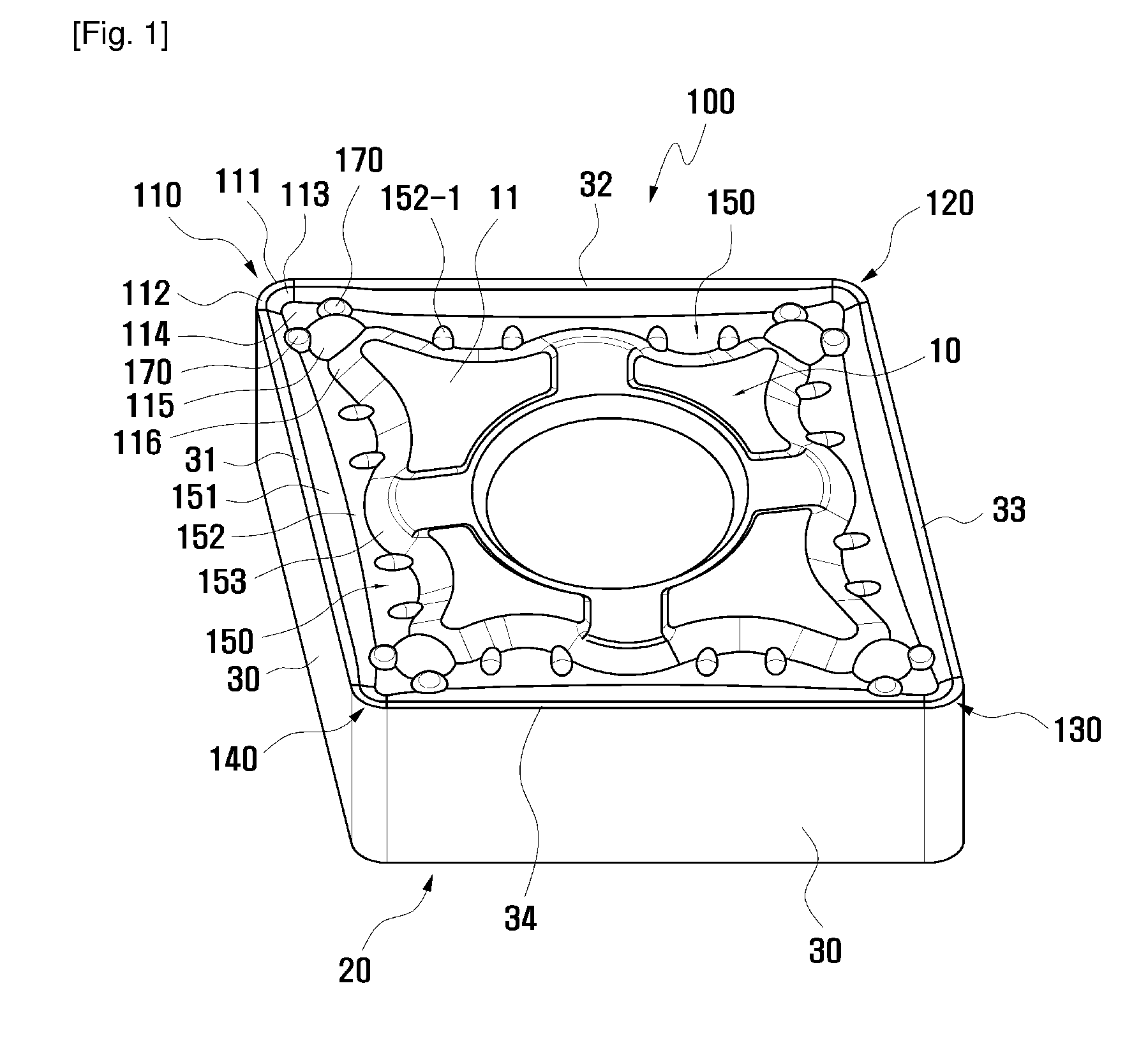
FIG. 1 and FIG. 2 are perspective view and plane view of a cutting insert according to the present invention and show a cutting insert having a structure being capable of controlling effectively chips generated on a work-piece.

A cutting insert 100 includes an upper surface 10, a lower surface 20 and side surfaces 30, each of four (4) corner cutting edge portions 110, 120, 130 and 140 is formed at an intersection between two adjacent side cutting edge portions (for example, 31 and 32).

As one example, the cutting insert 100 is an equilateral parallelogram member having a certain angled diamond shape. That is, as shown in FIG. 2, one side surface 30 of the cutting insert 100 has a certain acute angle with respect to an adjacent side surface.

The upper surface 10 and the lower surface 20 of the cutting insert 100 are formed with a substantial plane seating surface 11, this seating surf...


PUM

PropertyMeasurementUnit
distanceaaaaaaaaaa
distanceaaaaaaaaaa
distanceaaaaaaaaaa

Abstract

A cutting insert has an upper surface, a lower surface, a plurality of side surfaces connecting the upper surface and the lower surface and a central hole formed at a central portion thereof. The cutting insert has a flat seating surface formed on a highest level of the upper surface, a plurality of side cutting edge portions formed at intersections of the upper surface and the side surfaces, and a corner cutting edge portion formed at an intersection of two adjacent side cutting edge portions and having a cutting edge formed at a front end thereof. A land portion, a downward inclined surface, a corner bottom surface, a first protrusion, an upward inclined surface and the seating surface are formed on the corner cutting edge portion sequentially along a diagonal line directed from the cutting edge to the central hole. A pair of second protrusions are formed and disposed symmetrically on both sides of the diagonal line so that the corner bottom surface is surrounded by the downward inclined surface, the first protrusion, and the second protrusions, and the corner bottom surface has the smallest height and the seating surface has the largest height along the diagonal line.

Description

TECHNICAL FIELDThe present invention relates to a cutting insert, more particularly, to a cutting insert having a structure being capable of controlling effectively chips generated on a work-piece at the time of performing a cutting process for the work-piece.BACKGROUND ARTIn general, a machining tool is used in the field of cutting machining such as drilling, milling, and turning. Within the fields of drilling and milling, a tool having a rotary character is useful for machining a fixed and movable work-piece.On the contrary, a machining tool for turning machining is fixed and has the purpose of machining work-piece which is rotating. In general, the machining tool comprises a tool holder and a cutting insert fixed to a mounting surface of the tool holder through a clamping means and contacted with the work-piece.When a turning machining in which the machining tool is utilized is performed, chips generated on the work-piece by the cutting insert should be separated and removed natu...

Claims


Application Information

Patent Timeline
Patent Type & Authority Applications(United States)
IPC IPC(8): B23B27/16
CPCB23B27/141B23B2200/082Y10T407/235Y10T407/23B23B2200/087
Inventor PARK, HONG SIKCHO, HO-HYOUN
Owner TAEGUTEC
Why Eureka
Try Eureka