

Stack type battery
a battery and stack technology, applied in the field of stack type batteries, can solve the problems of deteriorating cycle performance, degrading cycle performance, and poor welding performance of the welded portion between the metal foil and the metal plate, so as to reduce the impact of welding welding deformation of the electrode plate lead tab, reduce the impact of welding welding, and reduce the effect of welding impa
Inactive Publication Date: 2011-03-24
SANYO ELECTRIC CO LTD
View PDF3 Cites 31 Cited by
- Summary
- Abstract
- Description
- Claims
- Application Information
AI Technical Summary
Benefits of technology
The present invention relates to a high-capacity lithium-ion battery that has a large number of stacks and achieves uniform connection resistance between electrode plates and current collector terminals. The technical effect of the invention is to prevent variations in the connection resistance values between electrode plates and a current collector terminal, inhibit the increase of battery size resulting from the increase of the area of the joining portions, and maintain the volumetric energy density to a desirable level.
Problems solved by technology
However, in this case, weldability of the welded portions between the metal foils and the metal plate tends to be poorer than that of the welded portions of the metal foils to each other, because of their thickness difference.
When the weldability becomes poor, the connection resistance between each of the electrode plates and the current collector terminal becomes non-uniform, causing variations in the current values flowing into the respective electrode plates especially when used at high rate.
As a consequence, uneven charge-discharge states arise and overdischarge and overcharge occur locally in the battery, deteriorating the cycle performance.
As a consequence, a difference arises between the electrode plates that finish discharging early and the other electrode plates, degrading the cycle performance.
However, a problem of this structure is that the area of the welded portion tends to be large, increasing the size of the battery as a whole.
Method used
View moreImage
Smart ImageViewing Examples

Examples
example
[0065]A stack type battery fabricated in the same manner as described in the foregoing embodiment was used as the stack type battery of this example.
[0066]The stack type battery fabricated in this manner is hereinafter referred to as Battery A of the invention.
Login to View More PUM
| Property | Measurement | Unit |
|---|---|---|
| thickness | aaaaa | aaaaa |
| thickness | aaaaa | aaaaa |
| thickness | aaaaa | aaaaa |
Abstract
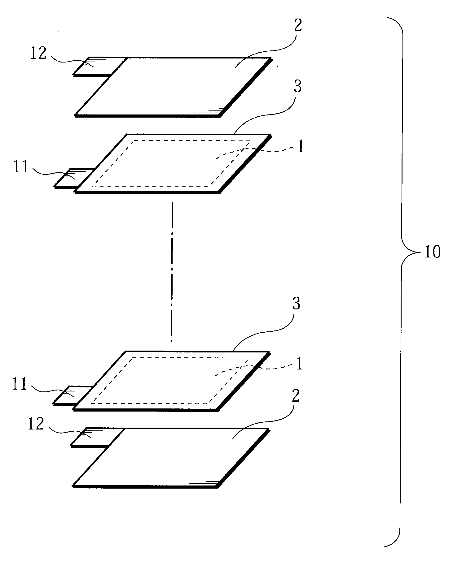
A penetrating portion (15P) is provided partially at a location in a positive electrode current collector terminal (15) to which positive electrode lead tabs (11) (electrode plate lead tabs) are joined, to form a current-collector-terminal-absent region (penetrating portion (15P)) and a current-collector-terminal-present region that are aligned in a perpendicular direction (a widthwise direction) to a connection direction of the positive electrode lead tabs (11). Only the plurality of the positive electrode lead tabs (11) are joined at a center weld point (32M) (first joining spot) in the current-collector-terminal-absent region, and the positive electrode lead tabs (11) are joined to the positive electrode current collector terminal 15 at each of left-side and right-side weld points 32L and 32R (second joining spot) in the current-collector-terminal-present region.
Description
BACKGROUND OF THE INVENTION[0001]1. Field of the Invention[0002]The present invention relates to stack type batteries, which have high capacity and high rate performance and are used for robots, electric vehicles, backup power sources and the like. More particularly, the invention relates to a high-capacity lithium-ion battery that has a large number of stacks requiring connection between a large number of electrode plate lead tabs and a current collector terminal, and that achieves uniform connection resistance between the electrode plates and the current collector terminal.[0003]2. Description of Related Art[0004]Power sources for robots and electric vehicle and backup power sources, for example, require high capacity and high rate performance. Lithium-ion batteries, which offer high energy density, have attracted attention as they meet such requirements.[0005]The battery configurations of the lithium-ion batteries are broadly grouped into two types. One is what is called a spiral...
Claims
Login to View More Application Information
Patent Timeline
 Patent Type & AuthorityApplications(United States)
IPC IPC(8): H01M10/02H01M10/052H01M50/533H01M50/534H01M50/536H01M50/54H01M50/562H01M50/566
CPCH01M2/22H01M2/26H01M2/266H01M2/305H01M4/1391Y02T10/7011H01M10/0413H01M10/0459H01M10/0525Y02E60/122H01M4/1393Y02E60/10H01M50/528H01M50/54Y02P70/50H01M50/536H01M50/566H01M50/534H01M50/562H01M50/533Y02T10/70
InventorFUJIWARA, MASAYUKISHINYASHIKI, YOSHITAKAMAEDA, HITOSHIFUNAHASHI, ATSUHIRO
OwnerSANYO ELECTRIC CO LTD