

Dental implant fixture
a technology for dental implants and fixtures, applied in dental surgery, medical science, osteosynthesis devices, etc., can solve the problems of affecting the whole stability of the implant fixture, deteriorating the fixing force, and damaging the prosthesis attached to the upper end, so as to prevent bone absorption and prevent re-operation.
- Summary
- Abstract
- Description
- Claims
- Application Information
AI Technical Summary
Benefits of technology
Problems solved by technology
Method used
Image

Examples
Embodiment Construction
Technical Problem
[0009]The present utility model provides a dental implant fixture capable of achieving initial fixing force in a cancellous bone, preventing bone absorption after implantation, and being inserted into a desired direction.
Technical Solution
[0010]According to an aspect of the present invention, there is provided a ˜˜
ADVANTAGEOUS EFFECTS
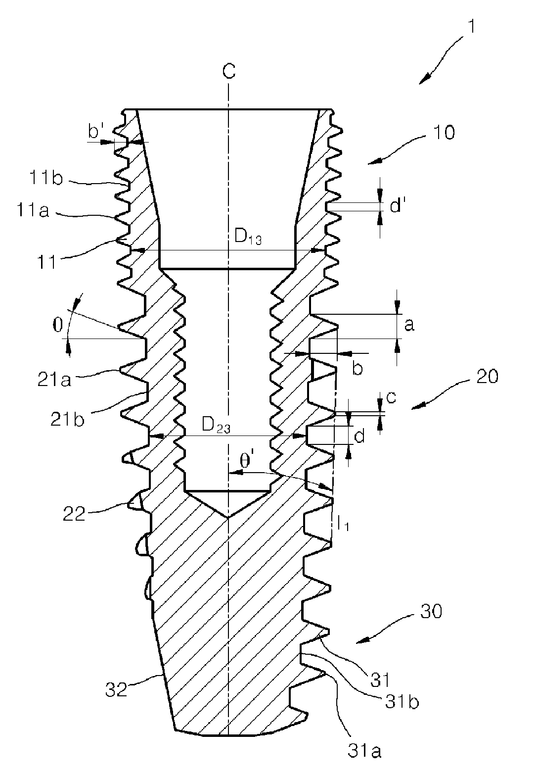
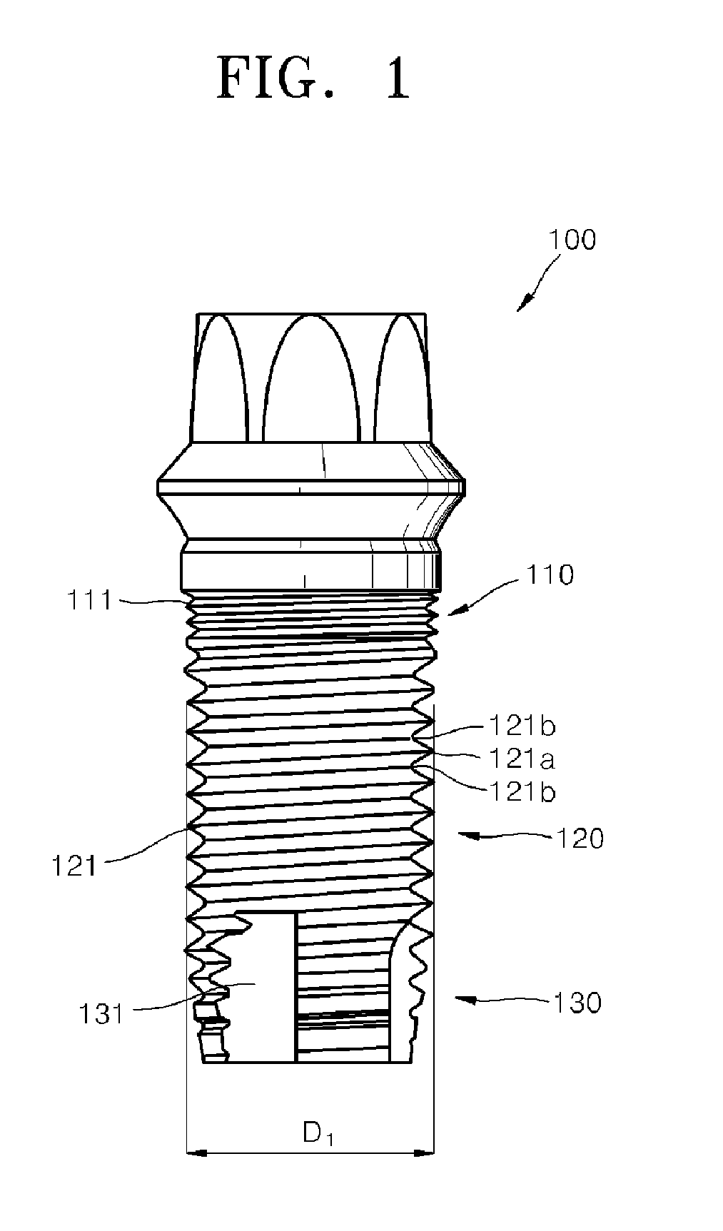
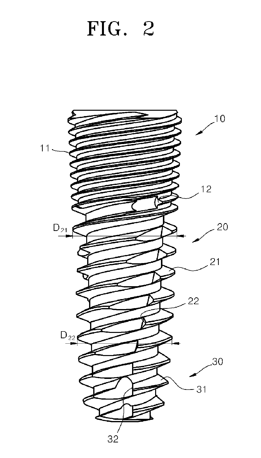
[0011]According to the dental implant fixture of the present invention described above, an outer diameter of a second screw thread implanted into a cancellous bone increases toward an upper side thereof, thereby achieving initial fixing force by applying a pressure to a bone tissue near the cancellous bone, and accordingly, preventing bone absorption after implantation.
[0012]The dental implant fixture formed with screw threads has a sharp cross section as a whole, so that the dental implant fixture can be inserted in a desired direction even when an implant hole is erroneously formed using a drill, thereby preventing a re-surgical opera...
PUM
 Abstract
Description
Claims
Application Information