System and method for mast vibration compensation

a vibration compensation and mast technology, applied in the field of systems and methods for mast vibration compensation, can solve the problems of increasing the complexity of the mast where the microwave radios are mounted, the limiting factor of the overall site cost, and the higher the installation cost, so as to achieve the effect of acceptable communication requirements

Active Publication Date: 2011-03-24
TELEFON AB LM ERICSSON (PUBL)
View PDF3 Cites 78 Cited by
  • Summary
  • Abstract
  • Description
  • Claims
  • Application Information

AI Technical Summary

Benefits of technology

[0007]An advantage with the present invention is that the requirement on the mast stability is greatly reduced compared to prior art systems.
[0008]Another advantage with the present invention is that the overall cost and complexity of the site is reduced in spite of the increased cost of the adaptive antenna as such.

Problems solved by technology

This leads to higher costs for the mast, and for the installation, and to a higher degree of complexity for the site in general.
When Microwave Radio Transmission is used as technology for mobile backhaul, the costs and complexity of the mast where the Microwave Radios are mounted is becoming a limiting factor for the overall site cost.
The requirement on the mechanical stability for the masts, where the Microwave Radios are fixed, is very tough and this is mainly due to the narrow-beam parabolic antennas used for this type of application.
As a consequence each mast must be stable and stiff, which makes it bulky and expensive.

Method used


Image

  • System and method for mast vibration compensation
  • System and method for mast vibration compensation
  • System and method for mast vibration compensation

Examples


Embodiment Construction

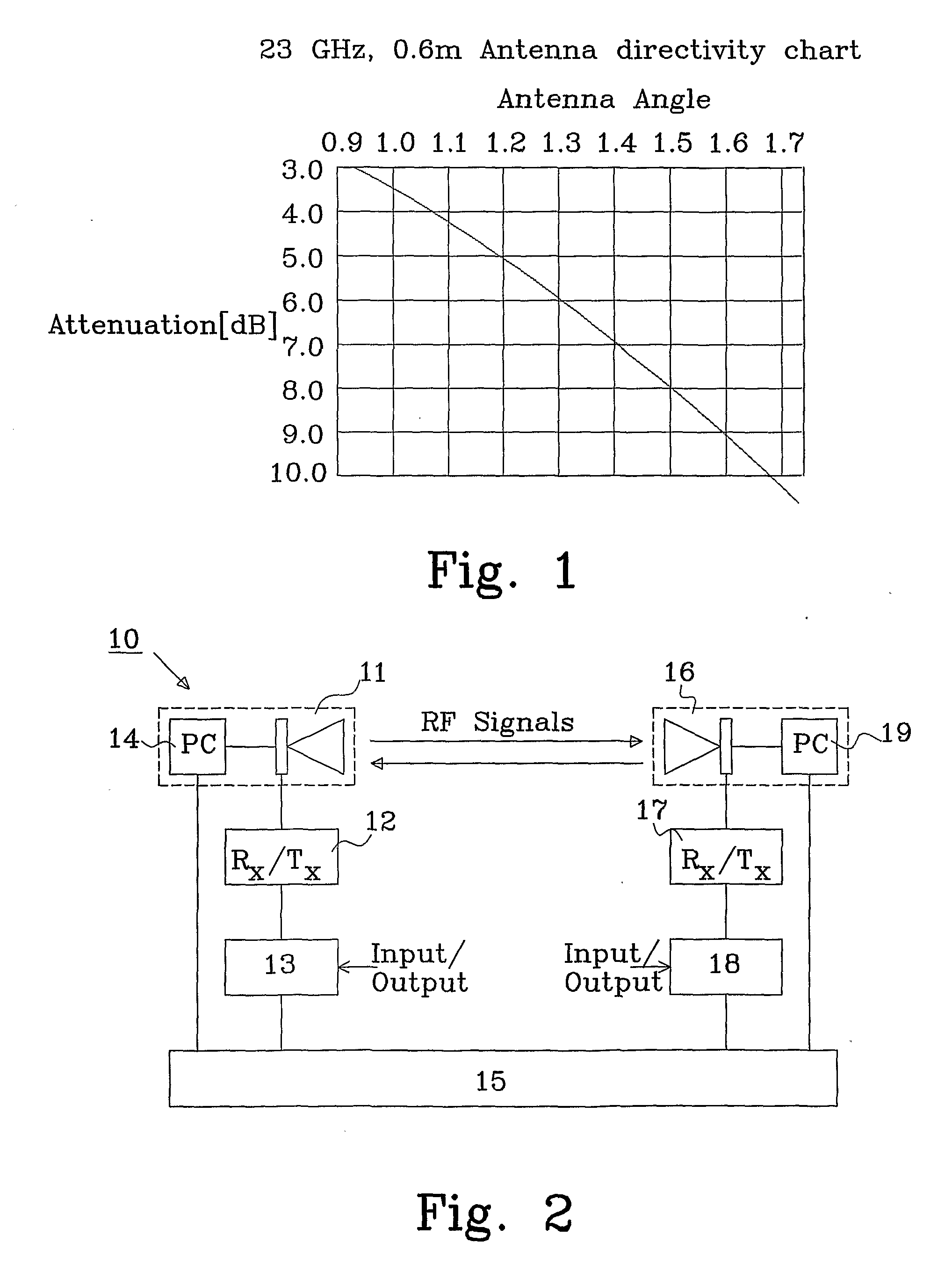
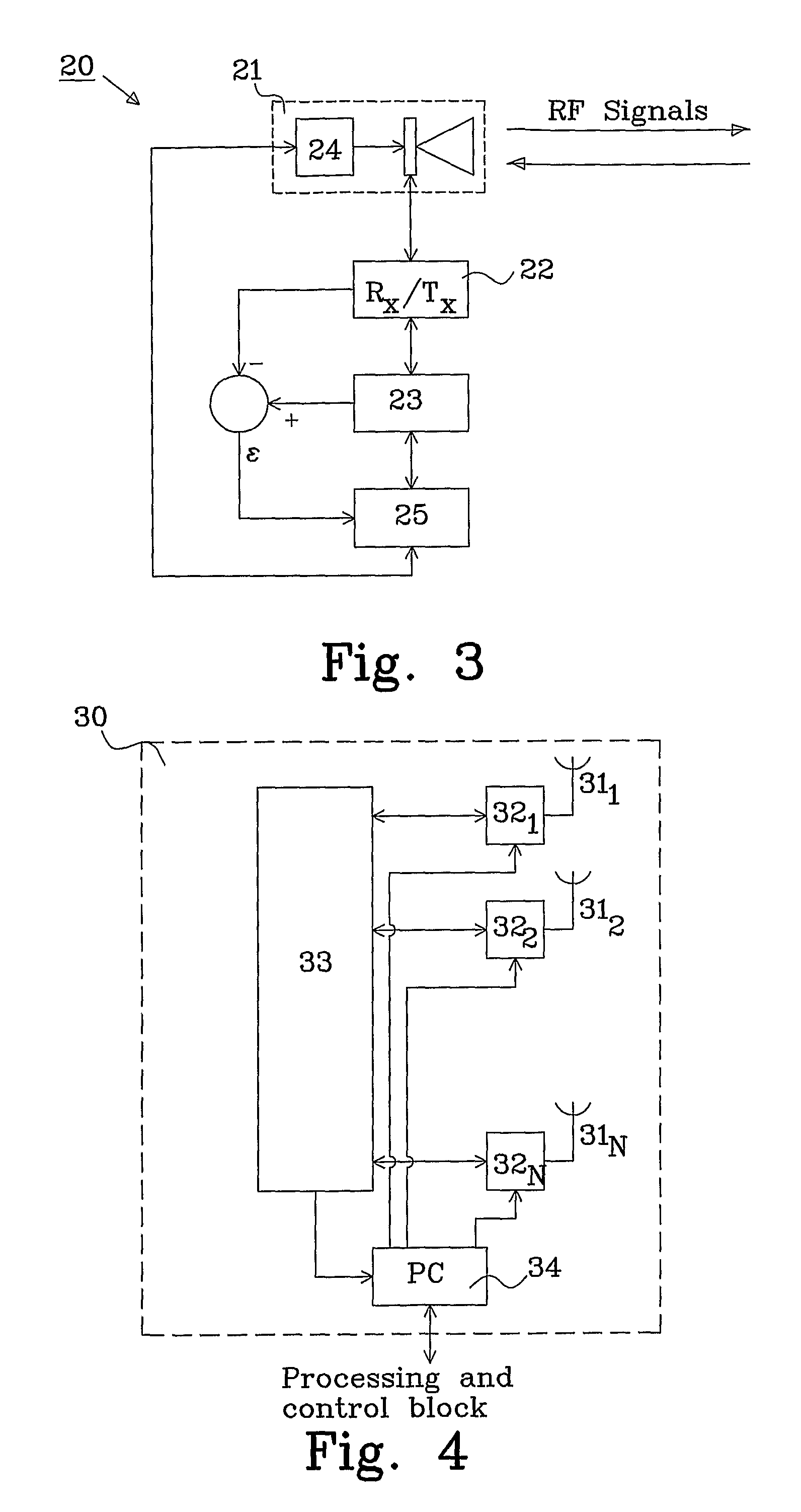
[0018]The proposed solution is to use adaptive antennas instead of the classical parabolic narrow-beam antennas and to reduce the requirement on the mast stability using the electronic control of the adaptive antenna to compensate the mechanical mast vibrations in a backhaul network, e.g. using microwave radio links.

[0019]Adaptive antennas with electronic beam shape control are commonly implemented in base stations to provide a suitable communication link between the base station and a user terminal, as described in U.S. Pat. No. 6,917,337 to Iida et al. Furthermore, adaptive antennas have also been used in point to point (PTP) communication systems to implement an interference mitigation method, as described in the published application US 2008 / 0049672 to Barak et al.

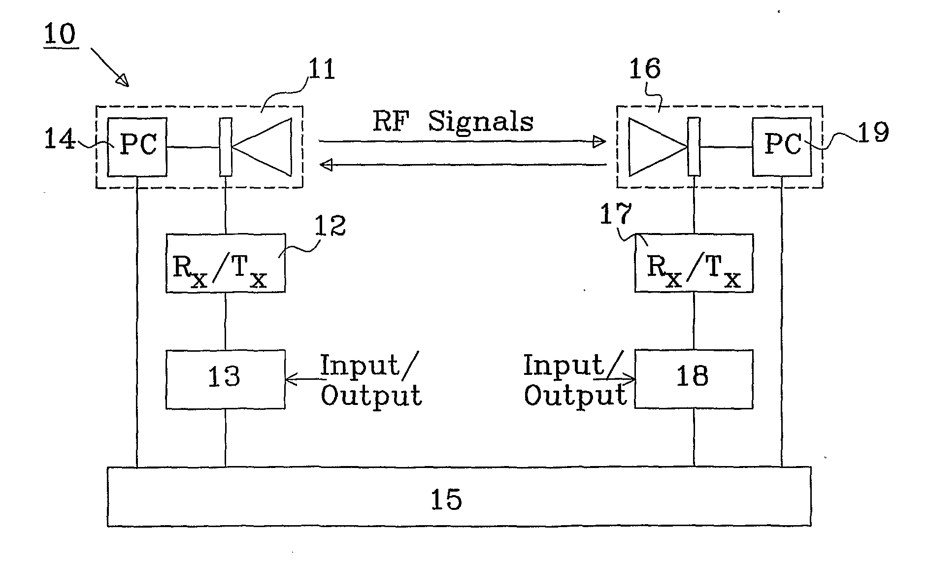
[0020]A typical half power beam-width angle for a classical high performance parabolic antenna is in the range 1° to 3° depending on frequency band and the dimensions of the antenna. This has a consequence that the ant...


PUM


Abstract

The present invention relates to a system for mast vibration compensation implemented in a communication system including a first node and a second node. The first node comprises a first adaptive antenna mounted in a mast; a receiver connected to said antenna; and a spatial and temporary processing system. The first adaptive antenna is controlled by a first correction signal generated in the spatial and temporary processing system. The correction signal is based on a parameter that indicates that a radio link alignment with a second node is degrading due to mechanical vibrations in the mast. The invention also relates to a method for mast vibration compensation.

Description

TECHNICAL FIELD[0001]The present invention relates to a system and a method for mast vibration compensation by adapting antenna beam direction and / or beam pattern, especially for compensating mast vibrations caused by external forces, such as wind.BACKGROUND[0002]In Microwave Radio Links, normally high gain parabolic antennas are used. This is a very common solution. Split outdoor units are very often mounted on masts that are part of the site installation. Each mast must have a very tough mechanical stability in order to allow the narrow beams of the high gain antennas to maintain aligned. This leads to higher costs for the mast, and for the installation, and to a higher degree of complexity for the site in general.[0003]When Microwave Radio Transmission is used as technology for mobile backhaul, the costs and complexity of the mast where the Microwave Radios are mounted is becoming a limiting factor for the overall site cost. The requirement on the mechanical stability for the mas...

Claims


Application Information

Patent Timeline
Patent Type & Authority Applications(United States)
IPC IPC(8): H04W24/00
CPCH01Q1/1242H01Q1/005H01Q1/185H01Q3/26H04B17/12H04B17/21
Inventor MARIOTTI, MARCO
Owner TELEFON AB LM ERICSSON (PUBL)
Why Eureka
Try Eureka