Control of exhaust flow in an engine including a particulate filter

Active Publication Date: 2011-03-31
FORD GLOBAL TECH LLC
View PDF15 Cites 18 Cited by
  • Summary
  • Abstract
  • Description
  • Claims
  • Application Information

AI Technical Summary

Benefits of technology

[0006]By performing the regeneration during and / or after engine shutdown, the particulate filter can be regenerated by an increased flow of oxygen to the particulate filter while avoiding potential increased emissions from a three-way catalyst in an exhaust tailpipe.
[0007]In one example, the vacuum may draw fresh air in a reverse direction through the filter. By controlling the system to draw fresh air into the particulate filter in a direction that is the reverse of a direction of exhaust flow during engine combustion, improved removal of soot may be achieved.
[0008]Yet another potential advantage of regenerating the filter during and / or after engine shutdown using stored vacuum is that a regeneration reaction can be delayed or advanced to a time when particulate filter conditions are appropriate for carrying out the regeneration reaction. For example, the stored vacuum may be stored until the particulate filter temperature becomes hot enough to carry out the regeneration reaction due to natural temperature increases that can occur after an engine shutdown. Further still, particulate filter regeneration may be selectively carried out under particular engine shutdown conditions (e.g., shutdowns in which filter regeneration is already commenced during engine running conditions, or shutdowns in which filter temperature is high enough), and not during others.

Problems solved by technology

As a consequence of diffuse flame propagation, fuel may not adequately mix with air prior to combustion, resulting in pockets of rich combustion that generate soot.
Further, DI engines may be susceptible to generating soot during high load and / or high speed conditions when there is a lack of sufficient air and fuel mixing.
For example, it can be difficult to maintain accurate emission control during particulate filter regeneration in a DI, spark-ignition engine.

Method used


Image

  • Control of exhaust flow in an engine including a particulate filter
  • Control of exhaust flow in an engine including a particulate filter
  • Control of exhaust flow in an engine including a particulate filter

Examples


Embodiment Construction

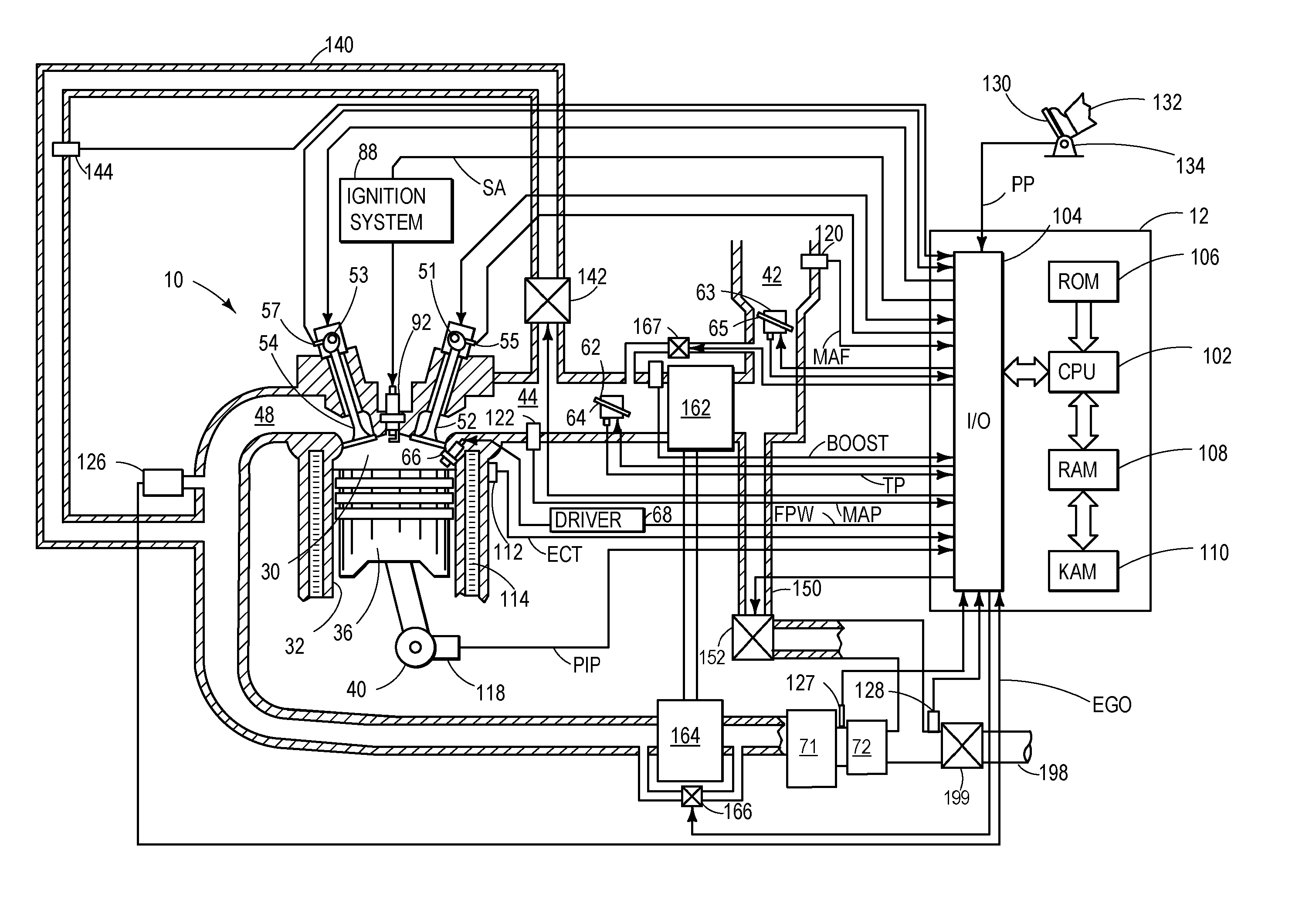
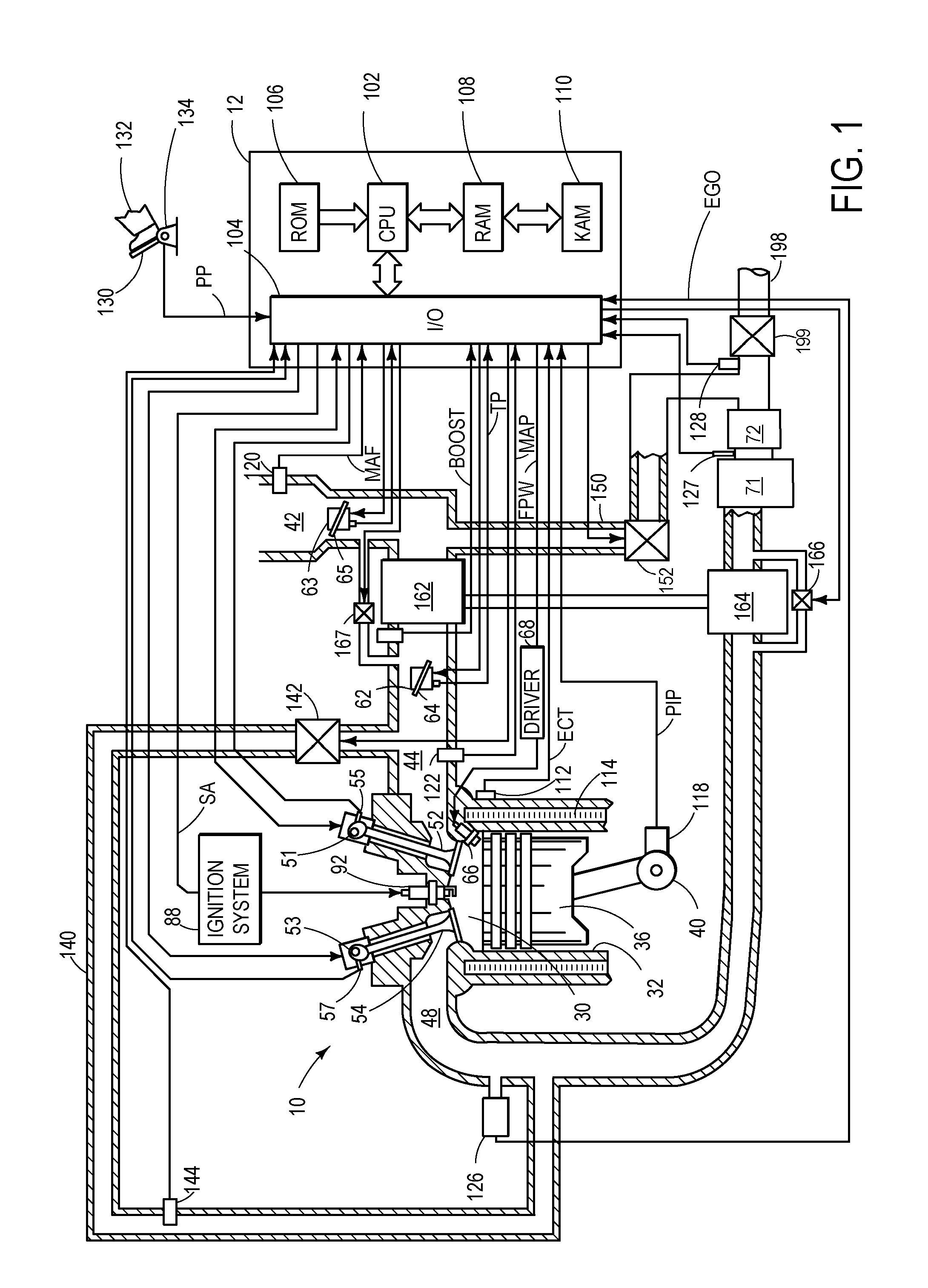
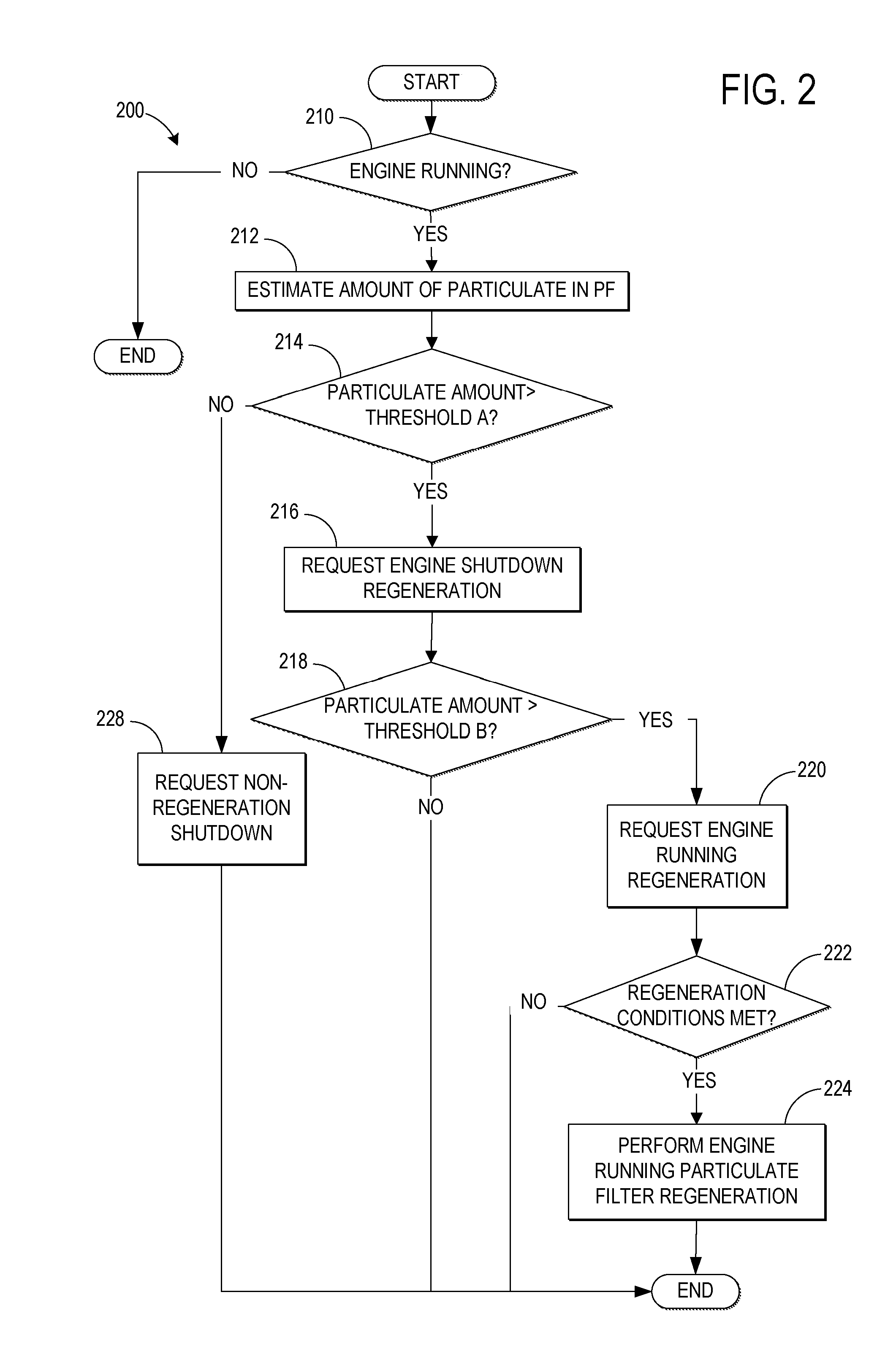
[0015]The following description relates to a method for regenerating a particulate filter in an engine, such as a direct injection gasoline engine. During a first operating condition of the engine, combustion in the engine may be carried out about stoichiometry and exhaust gas may flow from the engine in a first direction, to a particulate filter where soot generated by the engine is collected. During engine operation, vacuum generated by engine spinning (or pressure generated by turbocharger motion) may be stored in the intake system, such as in the intake manifold. Then during a subsequent engine shutdown (e.g., during engine spin-down after combustion has stopped, or during engine rest), the stored vacuum or pressure may be applied to generate regeneration flow to the filter. For example, stored vacuum may be used to draw fresh air into the filter from ambient atmosphere (e.g., via the tailpipe and / or engine inlet) in a second, reverse direction, to aid in filter regeneration. Al...


PUM


Abstract

Methods and systems for controlling operation of exhaust of an engine including a particulate filter are provided. One example method includes generating vacuum during engine operation, and storing the vacuum. The method further includes, during or after engine shutdown, drawing ambient air through the particulate filter via the vacuum.

Description

CROSS-REFERENCE TO RELATED APPLICATION[0001]This application claims priority to U.S. Provisional Patent Application Ser. No. 61 / 246,944, entitled “PARTICULATE FILTER REGENERATION DURING ENGINE SHUTDOWN,” filed Sep. 29, 2009, the disclosure of which is hereby incorporated by reference in its entirety and for all purposes.TECHNICAL FIELD[0002]The present application relates generally to an engine having an exhaust system which includes a particulate filter.BACKGROUND AND SUMMARY[0003]Direct injection (DI) engines may produce more soot than port fuel injected engines in part due to diffuse flame propagation. As a consequence of diffuse flame propagation, fuel may not adequately mix with air prior to combustion, resulting in pockets of rich combustion that generate soot. Further, DI engines may be susceptible to generating soot during high load and / or high speed conditions when there is a lack of sufficient air and fuel mixing.[0004]The inventors herein have recognized various issues in...

Claims


Application Information

Patent Timeline
IPC IPC(8): F02D43/00F01N3/00
CPCF01N3/0238F01N9/002F02B33/44F02M25/0704F02M25/0709Y02T10/121Y02T10/47F02M25/0707F02M26/05F02M26/06F02M26/02Y02T10/40Y02T10/12
Inventor VAN NIEUWSTADT, MICHIEL J.
Owner FORD GLOBAL TECH LLC
Why Eureka
Try Eureka