Damping force control type shock absorber

a technology of shock absorber and control type, which is applied in the direction of shock absorber, vibration damper, spring/damper, etc., can solve the problem of excessive damping force, and achieve the effect of appropriate damping force and simple structur

Active Publication Date: 2011-03-31
HITACHI ASTEMO LTD
View PDF7 Cites 31 Cited by
  • Summary
  • Abstract
  • Description
  • Claims
  • Application Information

AI Technical Summary

Benefits of technology

[0005]An object of the present invention is to provide a damping force control type shock absorber having a simple stru

Problems solved by technology

The damping force control mechanism disclosed in Japanese Patent Application Publication No. 2001-12534 suffers, however, from the problem that the contr

Method used


Image

  • Damping force control type shock absorber
  • Damping force control type shock absorber
  • Damping force control type shock absorber

Examples


Embodiment Construction

[0011]Embodiments of the present invention will be explained below in detail with reference to the accompanying drawings.

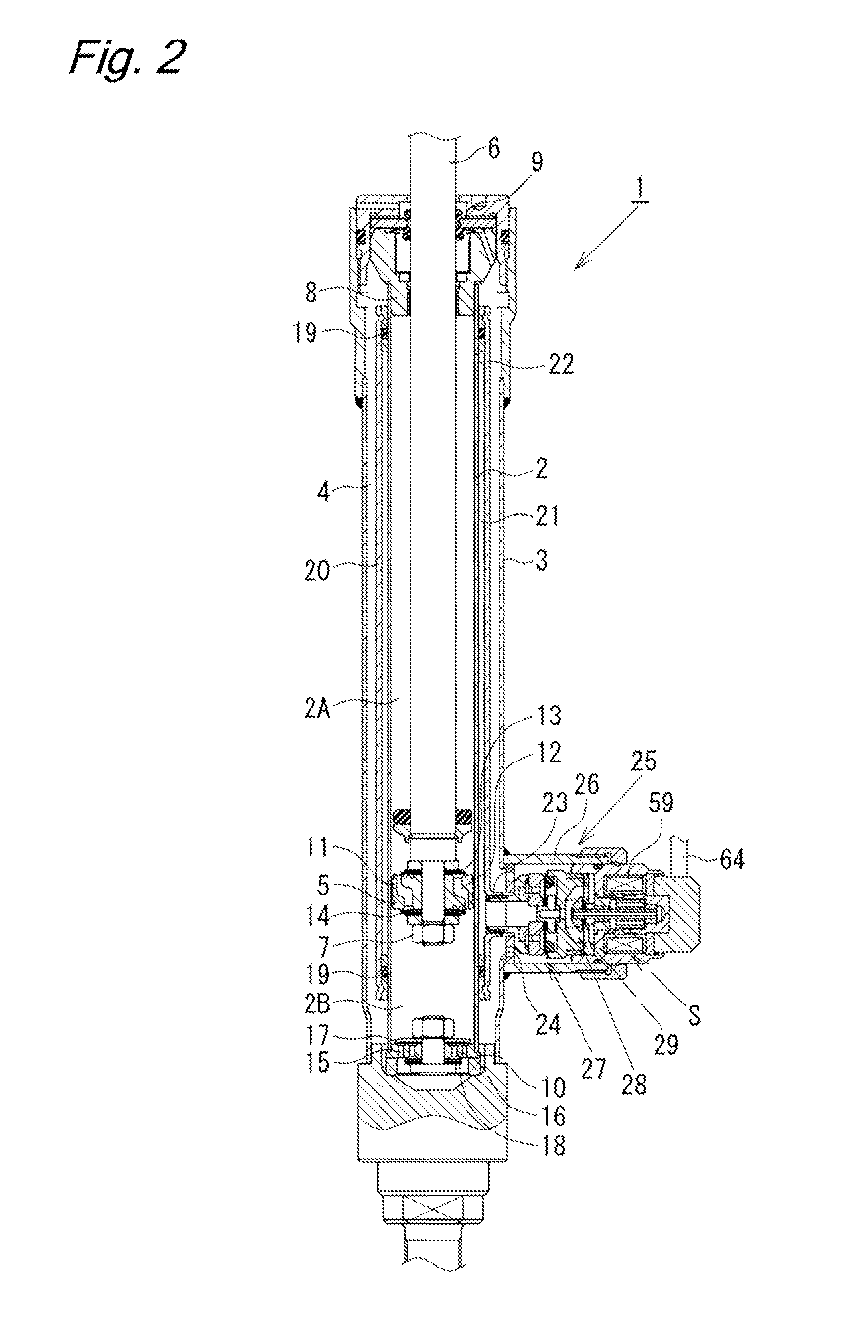
[0012]A first embodiment of the present invention will be explained with reference to FIGS. 1 and 2.

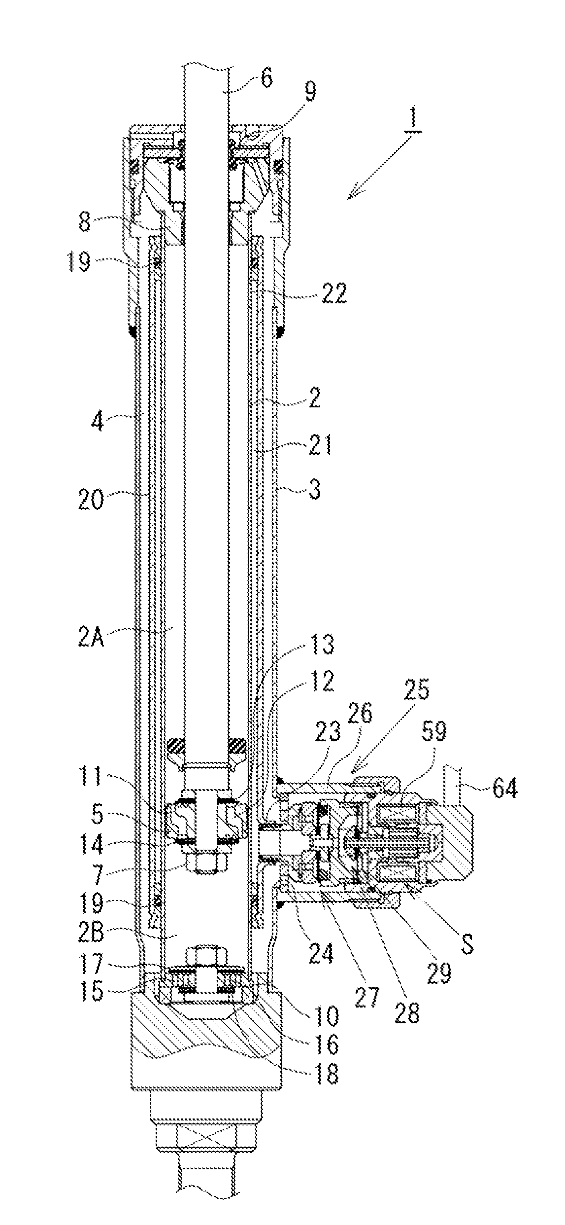
[0013]As shown in FIG. 2, a damping force control type shock absorber 1 according to this embodiment has a dual-tube structure comprising a cylinder 2 and an outer tube 3 provided outside the cylinder 2. A reservoir 4 is formed between the cylinder 2 and the outer tube 3. A piston 5 is slidably fitted in the cylinder 2. The piston 5 divides the interior of the cylinder 2 into two chambers, i.e. a cylinder upper chamber 2A and a cylinder lower chamber 2B. The piston 5 is connected with one end of a piston rod 6 by a nut 7. The other end portion of the piston rod 6 extends through the cylinder upper chamber 2A and further through a rod guide 8 and an oil seal 9, which are fitted to the upper end portion of the double-tube structure comprising the cylinder 2 and the ou...


PUM


Abstract

The flow of hydraulic fluid induced by sliding movement of a piston in a cylinder is controlled by a pilot-type main valve and a pilot valve, which is a pressure control valve, thereby generating damping force. By thrust from a solenoid actuator, the valve-opening pressure of the pilot valve is controlled, and the pressure in a pilot chamber is also controlled to control the valve-opening pressure of the main valve. When there is a failure, a valve body of the pilot valve is retracted to abut against a fail-safe disk by spring force of a valve spring. Thus, damping force is generated by the fail-safe disk at the downstream side of the pilot valve, and the valve-opening pressure of the main valve is also controlled by the fail-safe disk to obtain an appropriate damping force.

Description

BACKGROUND OF THE INVENTION[0001]The present invention relates to a damping force control type shock absorber capable of controlling damping force.[0002]Shock absorbers attached to suspension systems of automobiles or other vehicles include a damping force control type shock absorber designed to be capable of appropriately controlling damping force in accordance with road surface conditions, vehicle running conditions, etc. to improve ride quality and steering stability.[0003]In general, the damping force control type shock absorber includes a cylinder having a fluid sealed therein. A piston connected with a piston rod is slidably fitted in the cylinder. A damping force control mechanism is provided in a passage through which the fluid flows in response to sliding movement of the piston in the cylinder. Japanese Patent Application Publication No. 2001-12534 discloses a damping force control mechanism that generates damping force by controlling the flow of fluid through a pilot-type ...

Claims


Application Information

Patent Timeline
IPC IPC(8): F16F9/34
CPCF16F9/465F16F9/44F16F9/46
Inventor MURAKAMI, HIROSHI
Owner HITACHI ASTEMO LTD
Why Eureka
Try Eureka