Ultraviolet light emitting diode with ac voltage operation

Active Publication Date: 2011-03-31
NIITEK
View PDF1 Cites 59 Cited by
  • Summary
  • Abstract
  • Description
  • Claims
  • Application Information

AI Technical Summary

Benefits of technology

[0006]It is an object of the present invention to provide a UV or deep UV

Problems solved by technology

This greatly increases package size or requires additional c

Method used


Image

  • Ultraviolet light emitting diode with ac voltage operation
  • Ultraviolet light emitting diode with ac voltage operation
  • Ultraviolet light emitting diode with ac voltage operation

Examples


Example

[0040]The present invention is directed to a UV or Deep UV LED which is operable with AC voltage.

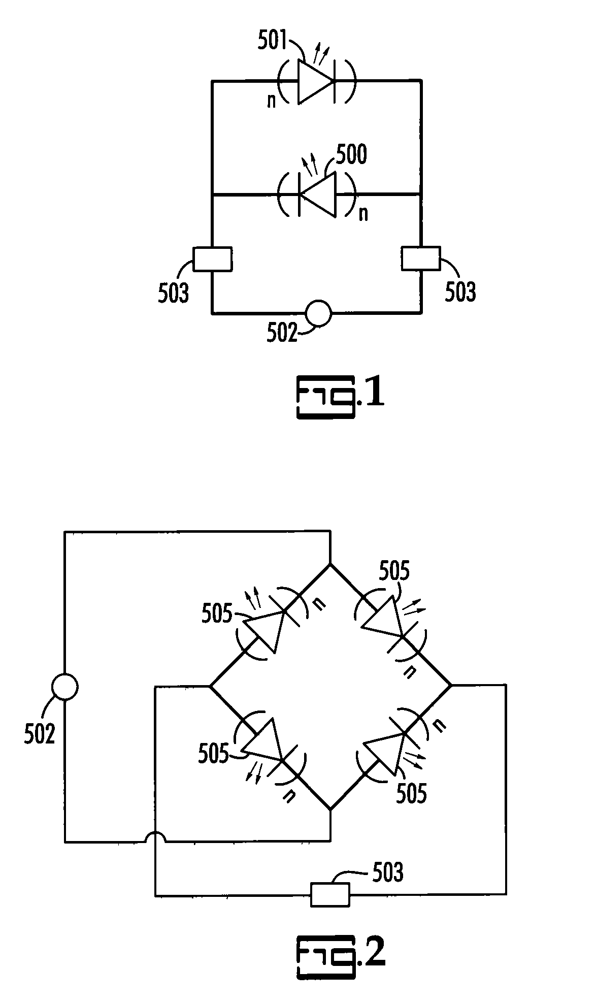
[0041]In the current invention, ultraviolet light emitting diodes with emission wavelengths from 200 nm to 400 nm, emit ultraviolet radiation under AC operation by wiring discrete LEDs with opposing polarity. More specifically, the cathode of one LED is in electrical contact with the anode of the other. When LEDs are connected to a low voltage AC circuit the LEDs thus connected illuminate alternately. In this configuration, one LED is biased by the positive voltage side of the AC cycle, referred to herein as forward biased, and the other LED is biased by the negative voltage cycle of the AC cycle, referred to herein as reverse biased. Since AC current usually runs at about 60 Hz each LED alternately emits ultraviolet light at a frequency of about 60 Hz with each being out of phase with the other. The result is illumination at about 120 Hz which appears to be continuous illumination to th...


PUM


Abstract

Ultraviolet light emitting illuminator, and method for fabricating same, comprises an array of ultraviolet light emitting diodes and a first and a second terminal. When an alternating current is applied across the first and second terminals and thus to each of the diodes, the illuminator emits ultraviolet light at a frequency corresponding to that of the alternating current. The illuminator includes a template with ultraviolet light emitting quantum wells, a first buffer layer with a first type of conductivity and a second buffer layer with a second type of conductivity, all deposited preferably over a strain-relieving layer. A first and second metal contact are applied to the semiconductor layers having the first and second type of conductivity, respectively, to complete the LED. The emission spectrum ranges from 190 nm to 369 nm. The illuminator may be configured in various materials, geometries, sizes and designs.

Description

CROSS-REFERENCE TO RELATED APPLICATIONS[0001]This application claims the benefit of pending PCT / US07 / 81625 filed Oct. 7, 2007 which, in turn, claims the benefit of expired U.S. Provisional Appl. No. 60 / 852,673 filed Oct. 18, 2006 and also claims the benefit of expired U.S. Provisional Appl. No. 60 / 935,491 filed Aug. 14, 2007 all of which are incorporated by reference. This application also claims the benefit of pending PCT / US07 / 81634 filed Oct. 17, 2007 which in turn claims the benefit of expired U.S. Provisional Patent Application No. 60 / 852,672 filed Oct. 18, 2006 both of which are incorporated herein by reference. The present application also claims the benefit of pending U.S. Provisional Patent Application No. 61 / 131,276 filed Jun. 9, 2008.BACKGROUND[0002]The present invention relates to single chip or multiple chip light emitting diodes (LEDs) or ultraviolet radiating illuminator, and more particularly to single or multiple chip ultraviolet light emitting diodes that operate un...

Claims


Application Information

Patent Timeline
IPC IPC(8): H01L33/06H01L33/62
CPCH01L27/153H01L33/62H01L33/32H01L2924/0002H01L2924/00
Inventor KHAN, ASIFADIVARAHAN, VINODFAREED, QHALID
Owner NIITEK
Why Eureka
Try Eureka