Device For And Method Of Determining Residence Time Distributions

a technology of residence time and distribution method, which is applied in the direction of ceramic shaping apparatus, manufacturing tools,auxillary shaping apparatus, etc., can solve the problems of difficult to determine process material properties, difficult to determine extensive mapping of rtd's as a function of screw design, operating characteristics, etc., and achieves the effect of less prone to errors and easy handling

Inactive Publication Date: 2011-03-31
MONTANUNIV LEOBEN
View PDF2 Cites 5 Cited by
  • Summary
  • Abstract
  • Description
  • Claims
  • Application Information

AI Technical Summary

Benefits of technology

[0004]Therefore, there may be a need to provide a device for and a method of determinin

Problems solved by technology

While this procedure is quite acceptable, it tends to be very time consuming and relatively expensive.
As a result extensive mappings

Method used


Image

  • Device For And Method Of Determining Residence Time Distributions
  • Device For And Method Of Determining Residence Time Distributions
  • Device For And Method Of Determining Residence Time Distributions

Examples


Embodiment Construction

[0056]The illustration in the drawings is schematically. In different drawings, similar or identical elements are provided with similar or same reference signs.

[0057]In the following, referring to FIGS. 1 to 6, an extruder and a method for determining residence time distribution is described.

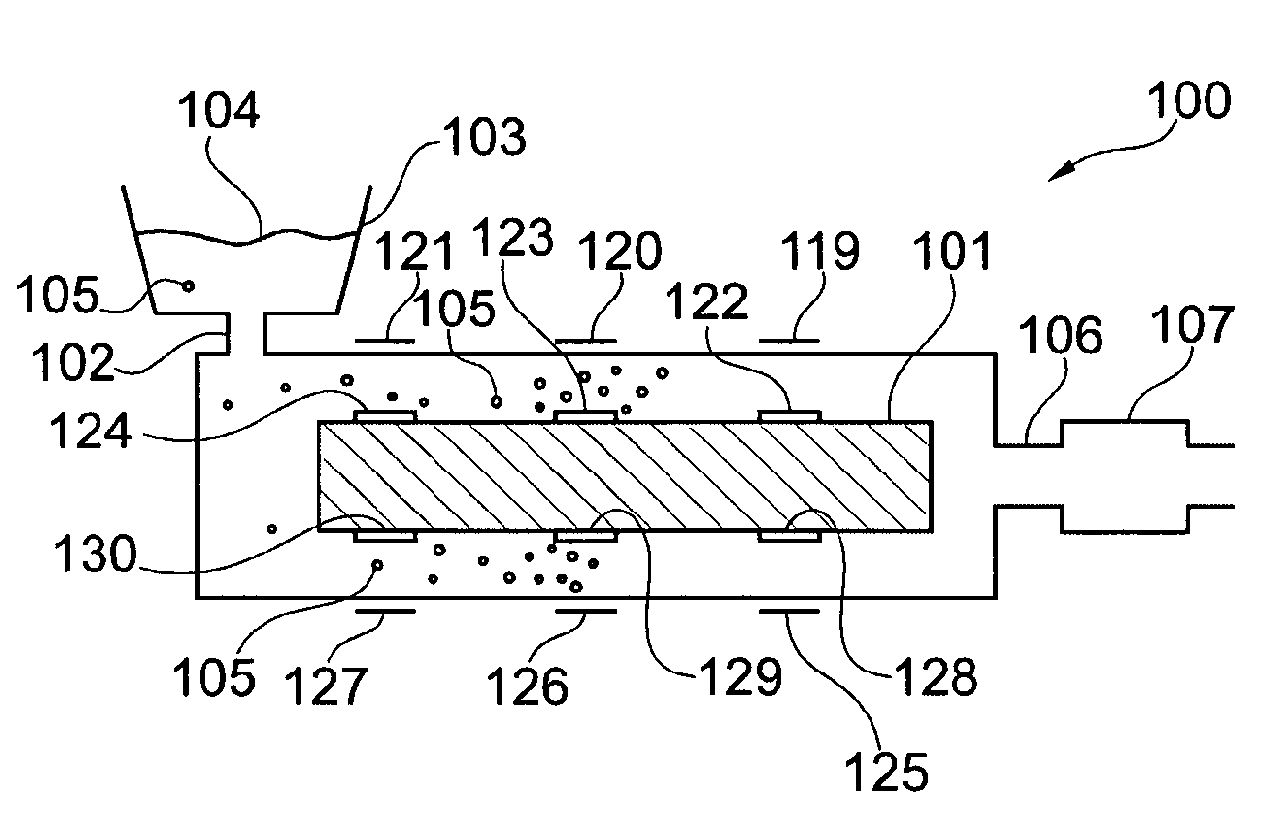
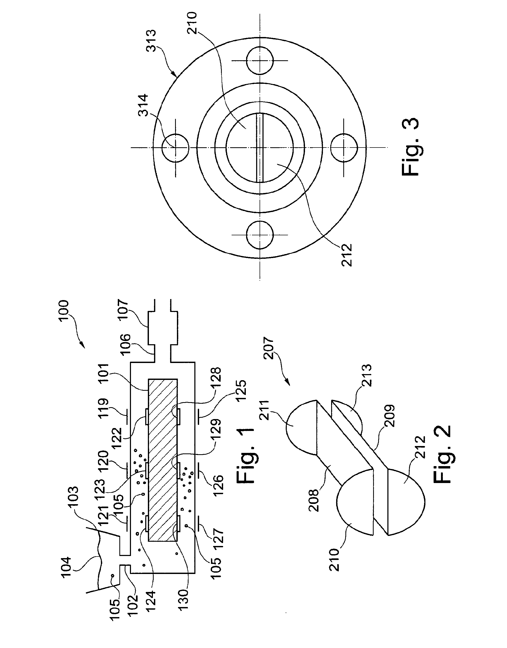
[0058]FIG. 1 schematically shows an extruder or extruder device 100, having a screw 101 which is used to move a molding batch, e.g. a polymer, through the extruder. The extruder 100 further comprises an input 102, which is connected to a container 103. In FIG. 1 the molding batch is schematically shown as 104 in the container 103. Into the molding batch an indicator or tracer is introduced, by introducing a pressed tracer pellet. The pressed tracer pellet is then grinded to a plurality of tracer particles during the path through the extruder, which grinded particles are schematically shown as the dots 105 in the molding batch. For illustration a further tracer pellet 105 is shown in the containe...


PUM

PropertyMeasurementUnit
Temperatureaaaaaaaaaa
Angleaaaaaaaaaa
Fractionaaaaaaaaaa

Abstract

A method of determining a residence time distribution comprises mixing a molding batch (104) and a tracer (105), wherein the tracer has a ferroelectric curie temperature above 120° C., and transmitting the mixture through a capacitor (107). Further, the method comprises measuring a capacitance of the capacitor, and determining a residence time distribution based on the measured capacitance. In particular, the ferroelectric curie temperature of the tracer may be above 150° C. and preferably the ferroelectric curie temperature of the tracer is above 200° C.

Description

FIELD OF THE INVENTION[0001]The invention relates to a device for and a method of determining a residence time distribution. Further, the invention relates to a computer-readable medium and to a program element. In particular, the invention relates to a method of determining a residence time distribution of a molding batch in an extruder.BACKGROUND OF THE INVENTION[0002]From “A New Method for On-line Determination of Residence Time Distributions in Extruders”, J. Golba, Polymer Physics & Engineering Branch Corporate Research and Development Center Schenectady, New York Technical Papers, Regional Technical Conference—Society of Plastics Engineers (1980) p. 83 to 87, it is known that the experimental determination of residence time distributions (RTD) is a critically important aspect of most analyses of the extrusion process. In essence, these distributions quantify the thermal and deformational histories experienced by the polymer system during processing. Such considerations are not...

Claims


Application Information

Patent Timeline
IPC IPC(8): B29C47/92B29C48/92
CPCB29C47/0009B29C47/1063B29C47/92B29C2947/92009B29C2947/92066B29C2947/92104B29K2105/0005B29C2947/92247B29C2947/92276B29C2947/9238B29C2947/92409B29C2947/92485B29C2947/92238B29C48/03B29C48/29B29C48/762B29C48/92B29C2948/92009B29C2948/92066B29C2948/92104B29C2948/92238B29C2948/92247B29C2948/92276B29C2948/9238B29C2948/92409B29C2948/92485
Inventor LEDERER, KLAUSLEDERER, BEATRIXREINBERGER, WOLFGANG
Owner MONTANUNIV LEOBEN
Why Eureka
Try Eureka