Amalgam support in an inductively coupled discharge lamp

Inactive Publication Date: 2011-03-31
OSRAM SYLVANIA INC
View PDF11 Cites 21 Cited by
  • Summary
  • Abstract
  • Description
  • Claims
  • Application Information

AI Technical Summary

Benefits of technology

[0008]An object of the present invention is to provide a novel amalgam support for an inductively coupled d

Problems solved by technology

One of the problems with this technique is that coupling to the amalgam-bearing loop reduces the efficiency of the plasma coupling.
One of the problems with this technique is the cumbersome manufacturing steps needed to provide an attachment location on the surface

Method used


Image

  • Amalgam support in an inductively coupled discharge lamp
  • Amalgam support in an inductively coupled discharge lamp
  • Amalgam support in an inductively coupled discharge lamp

Examples


Example

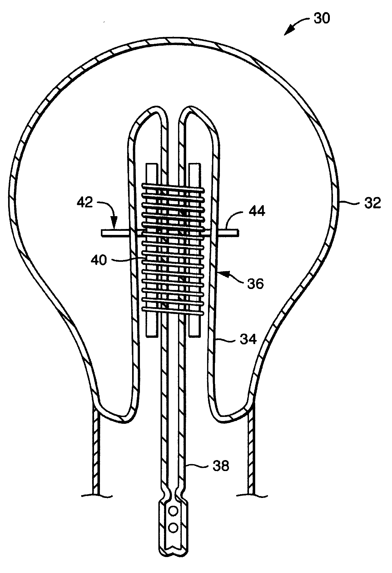
[0019]With reference now to FIG. 3, an inductively coupled fluorescent discharge lamp 30 of one embodiment of the present invention includes a light transmissive envelope 32 having a re-entrant cavity 34, where the re-entrant cavity 34 has an outer surface 36 inside the envelope 32. An exhaust tube 38 is inside the re-entrant cavity 34 and opens to an inside of the envelope. An excitation coil 40 is also in the re-entrant cavity. An amalgam 42 is provided on a metallic C-shaped spring clip 44 on the outer surface 36 of the re-entrant cavity 34, where the spring clip 44 is attached to the outer surface by a spring action of the spring clip on the outer surface of the re-entrant cavity. (“C-shaped” means not a closed circle; having a gap in the metal forming the clip through which the re-entrant cavity fits when placing the clip onto the re-entrant cavity by overcoming the spring force of clip. The open C-shape is meant to avoid coupling to the induction field.)

[0020]Depending on the ...


PUM


Abstract

An inductively coupled fluorescent discharge lamp includes a light transmissive envelope having a re-entrant cavity that has an outer surface inside the envelope, and an excitation coil inside the re-entrant cavity, and a spring clip that is attached to the outer surface of the re-entrant cavity by spring action of the spring clip on the outer surface, where the spring clip includes an amalgam. The spring clip may include a layer of the amalgam plated on a surface of the clip, or an amalgam-bearing flag attached to the clip.

Description

BACKGROUND OF THE INVENTION[0001]The present invention is directed to an inductively coupled fluorescent discharge lamp, and more specifically to an amalgam support in such a lamp.[0002]With reference to FIG. 1, a conventional inductively coupled fluorescent discharge lamp 10 may include a light transmissive envelope 12 having a re-entrant cavity 14 with an exhaust tube 16 and an excitation coil 18 inside the re-entrant cavity.[0003]The light output of the inductively coupled fluorescent discharge lamp is dependent on the mercury vapor pressure within the lamp envelope. Alloys of low temperature melting metals that amalgamate with the mercury are often placed within such lamps to regulate the mercury vapor pressure within the lamp. When the lamp is turned on, the lumen output is significantly reduced until the amalgam is heated to a point where it releases sufficient mercury vapor to permit efficient lamp operation. This may require from several to many minutes depending on the lamp...

Claims


Application Information

Patent Timeline
IPC IPC(8): H01J61/24
CPCH01J61/24H01J65/048H01J61/30
Inventor SPEER, RICHARD S.SERRE, JEFFERY
Owner OSRAM SYLVANIA INC
Why Eureka
Try Eureka