Discharge lamp lighting apparatus

Inactive Publication Date: 2011-03-31
PANASONIC CORP
View PDF8 Cites 10 Cited by
  • Summary
  • Abstract
  • Description
  • Claims
  • Application Information

AI Technical Summary

Benefits of technology

[0026]According to the present invention, it is possible to suppress a variation attributable to a drive frequency of a polarity inversion (inverter) circuit, to suppr

Problems solved by technology

Meanwhile, in the case of the conventional circuit, electrodes of a discharge lamp (La) may not be evenly warmed up immediately after lighting of the discharge lamp is started by use of the resonance circuit 4, in some cases.
This causes large damage on the electrodes of the lamp.
Moreover, the electrodes of the lamp may be severely damaged if the lamp switches to steady lighting (low-frequency lighting

Method used


Image

  • Discharge lamp lighting apparatus
  • Discharge lamp lighting apparatus
  • Discharge lamp lighting apparatus

Examples


Example

First Embodiment

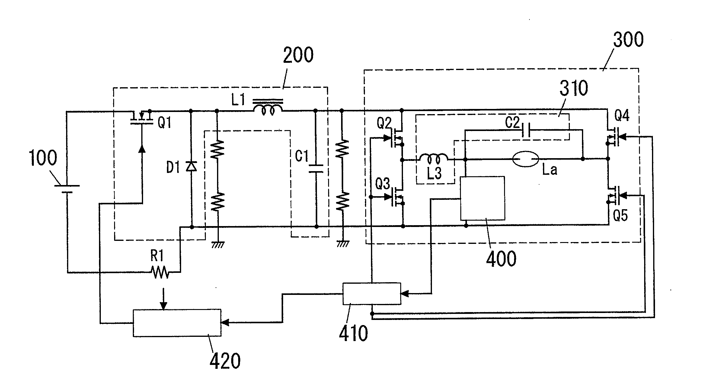
[0050]As shown in FIG. 4, this first embodiment includes a down-converter circuit 200 that steps down direct current power inputted from a direct current power source 100 and outputs the stepped down current, and an inverter circuit 300 that converts the direct current power outputted from the down-converter circuit 200 into alternating current power and supplies the alternating current power to a discharge lamp La. The discharge lamp La in this first embodiment is a high-pressure discharge lamp which is also called a HID (high intensity discharge) lamp. The high-pressure discharge lamp of this type includes a high-pressure mercury lamp or a metal halide lamp, for example.

[0051]The down-converter circuit 200 is a well-known circuit also called a back converter or a step-down-converter. The down-converter circuit 200 includes a series circuit and a diode D1. The series circuit is formed of a switching element Q1, an inductor L1, and an output capacitor C1, and is conn...

Example

Second Embodiment

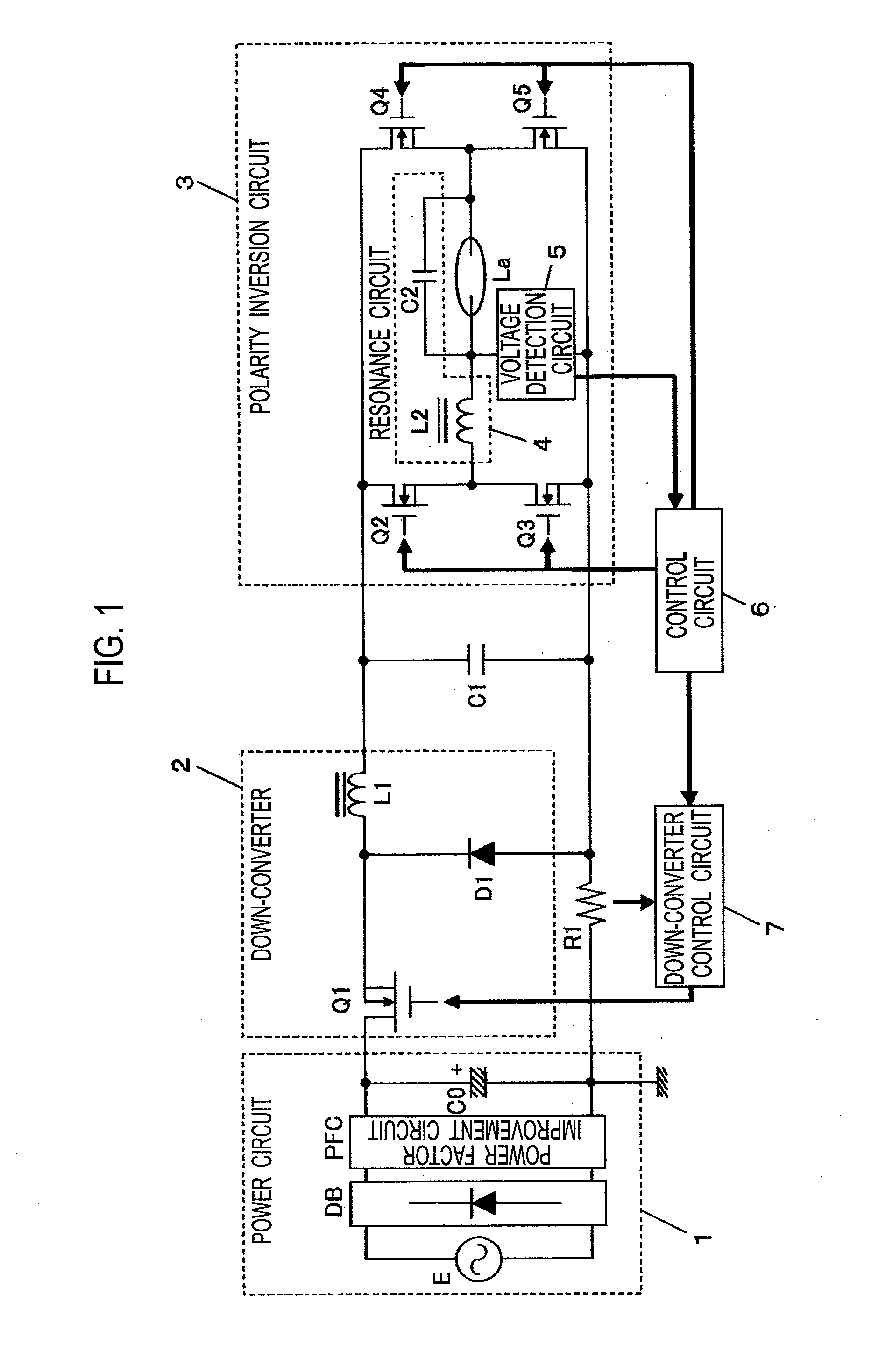
[0066]FIG. 11 shows a configuration of a high-pressure discharge lamp lighting device of a second embodiment of the present invention. The high-pressure discharge lamp lighting device of this second embodiment includes a power circuit 1 for obtaining a direct current voltage from a commercial alternating current power source E, a down-converter 2 that steps down the direct current voltage to be supplied from the power circuit 1, and a polarity inversion circuit 3 that inverts the polarity of an output voltage from the down-converter 2. A serial resonance circuit 4 formed of a capacitor C2 and an inductor L2 is connected to an output of the polarity inversion circuit 3, and a high-pressure discharge lamp La is connected to both ends of the capacitor C2. In addition, the high-pressure discharge lamp lighting device includes a control circuit 6 and a down-converter control circuit 7.

[0067]The power circuit 1 includes a diode bridge DB that performs full-wave rectificat...

Example

Third Embodiment

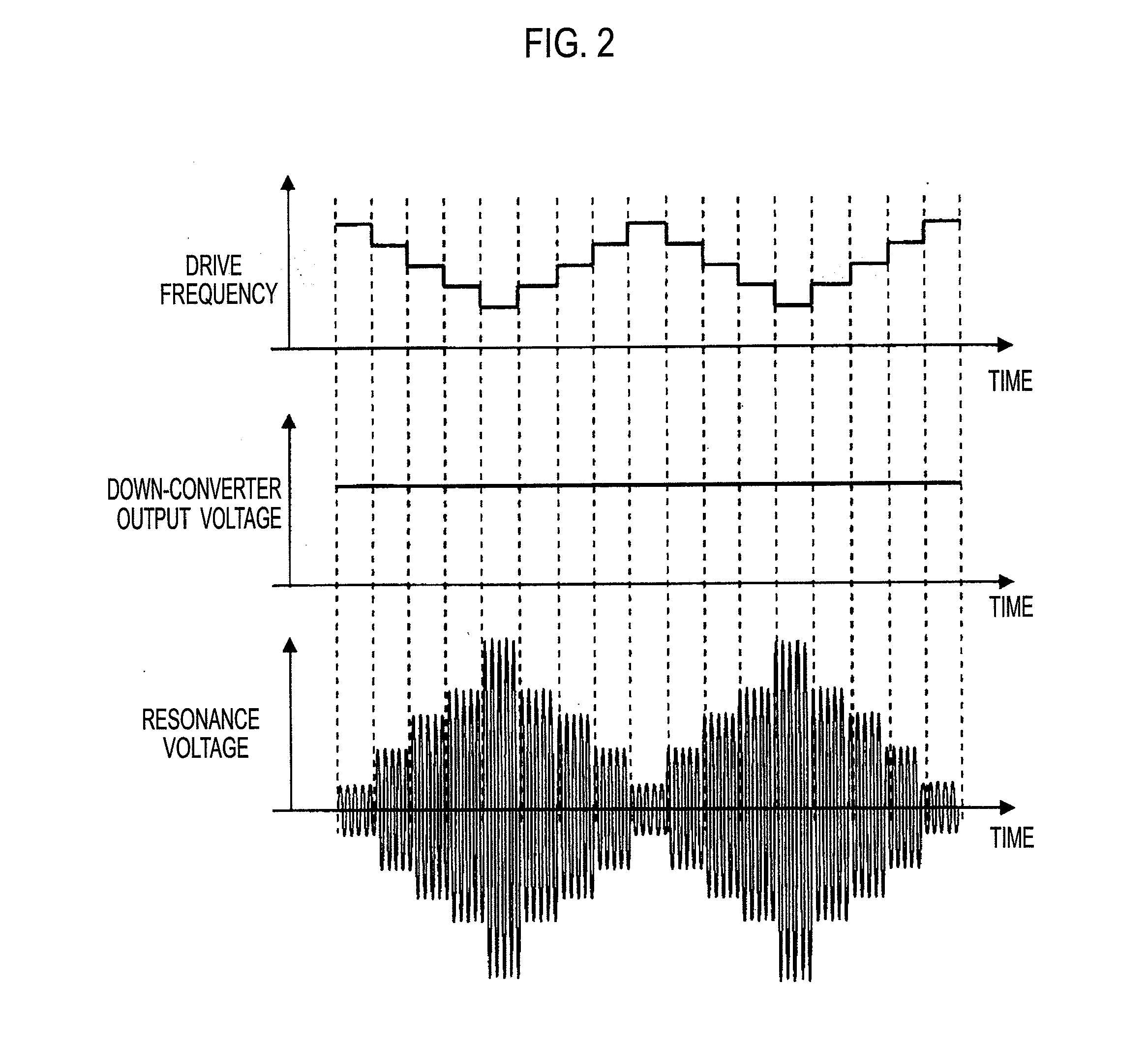
[0079]FIG. 14 and FIG. 15 each show a drive frequency of a polarity inversion circuit, an output voltage from a down-converter, and a resonance voltage to be applied to a discharge lamp in a high-pressure discharge lamp lighting device of a third embodiment of the present invention. A circuit configuration is the same as FIG. 11.

[0080]A difference from the second embodiment is as follows. Specifically, the sweeping of the drive frequency of the polarity inversion circuit is performed so that the drive frequency is brought gradually closer to a resonance point of the resonance circuit from a frequency A higher than the resonance point. After reaching a desired resonance voltage Vp, in a case of FIG. 14, the drive frequency of the polarity inversion circuit is gradually increased and returns to the frequency A. In the case of FIG. 15, the sweeping of the drive frequency of the polarity inversion circuit is performed again from the frequency A. By varying the output vol...


PUM


Abstract

In order to suppress a peak of an excessive current and suppress a variation in a resonance voltage of a resonator, which are likely to occur immediately after a discharge lamp starts lighting, in a case where a high-frequency current continuously flows asymmetrically with respect to a zero current instead of flowing symmetrically on positive and negative sides immediately after the lighting since electrodes of the discharge lamp are not evenly warmed, the resonance voltage and the high-frequency current are finely adjusted in a resonance voltage and high-frequency current setting method including setting a drive frequency of an inverter circuit and varying output from a down-converter.

Description

TECHNICAL FIELD[0001]The present invention relates to a lighting device for a discharge lamp for lighting a high intensity discharge lamp such as a high-pressure mercury lamp and a metal halide lamp.BACKGROUND ART[0002]High intensity discharge lamps such as metal halide lamps have become increasingly used as various light sources in recent years, and such lamps are required to have long operating life.[0003]FIG. 1 is a circuit diagram of a conventional discharge lamp lighting device for lighting a high-pressure discharge lamp. FIG. 2 is an operation waveform chart at a time when the lighting device shown in FIG. 1 starts operating, and shows temporal changes in a drive frequency of a polarity inversion (inverter) circuit, an output voltage of a down-converter, and a resonant voltage applied to the discharge lamp. In FIG. 1 and FIG. 2, a voltage supplied from a direct current power source 1 is controlled with a down-converter 2. A polarity inversion (inverter) circuit 3 is provided a...

Claims


Application Information

Patent Timeline
IPC IPC(8): H05B37/02
CPCH05B41/38H05B41/2886
Inventor NAKADA, KATSUYOSHINAKANO, TOMOYUKIHASEGAWA, JUNICHIWATANABE, KOJI
Owner PANASONIC CORP
Why Eureka
Try Eureka