Display device

Active Publication Date: 2011-03-31
JOLED INC
View PDF20 Cites 31 Cited by
  • Summary
  • Abstract
  • Description
  • Claims
  • Application Information

AI Technical Summary

Benefits of technology

[0034]Application of the present invention under this circumstance provides more sets in the specific color pixel that is susceptible to a dark dot or that has high relative luminosity factor rather than providing the same number of sets, thus easing the tradeo

Problems solved by technology

However, panels are susceptible to display defects such as dark dots in which light emitting isn't performed normally caused by dust attached to OLEDs and other electro-optical elements during manufacture.
These display defects are detrimental to providing improved yield of the display device, hampering the cost r

Method used


Image

  • Display device
  • Display device
  • Display device

Examples


Embodiment Construction

[0052]Embodiments of the present invention will be described below with reference to the accompanying drawings taking, as an example, a case in which the present invention is applied to an organic EL display device.

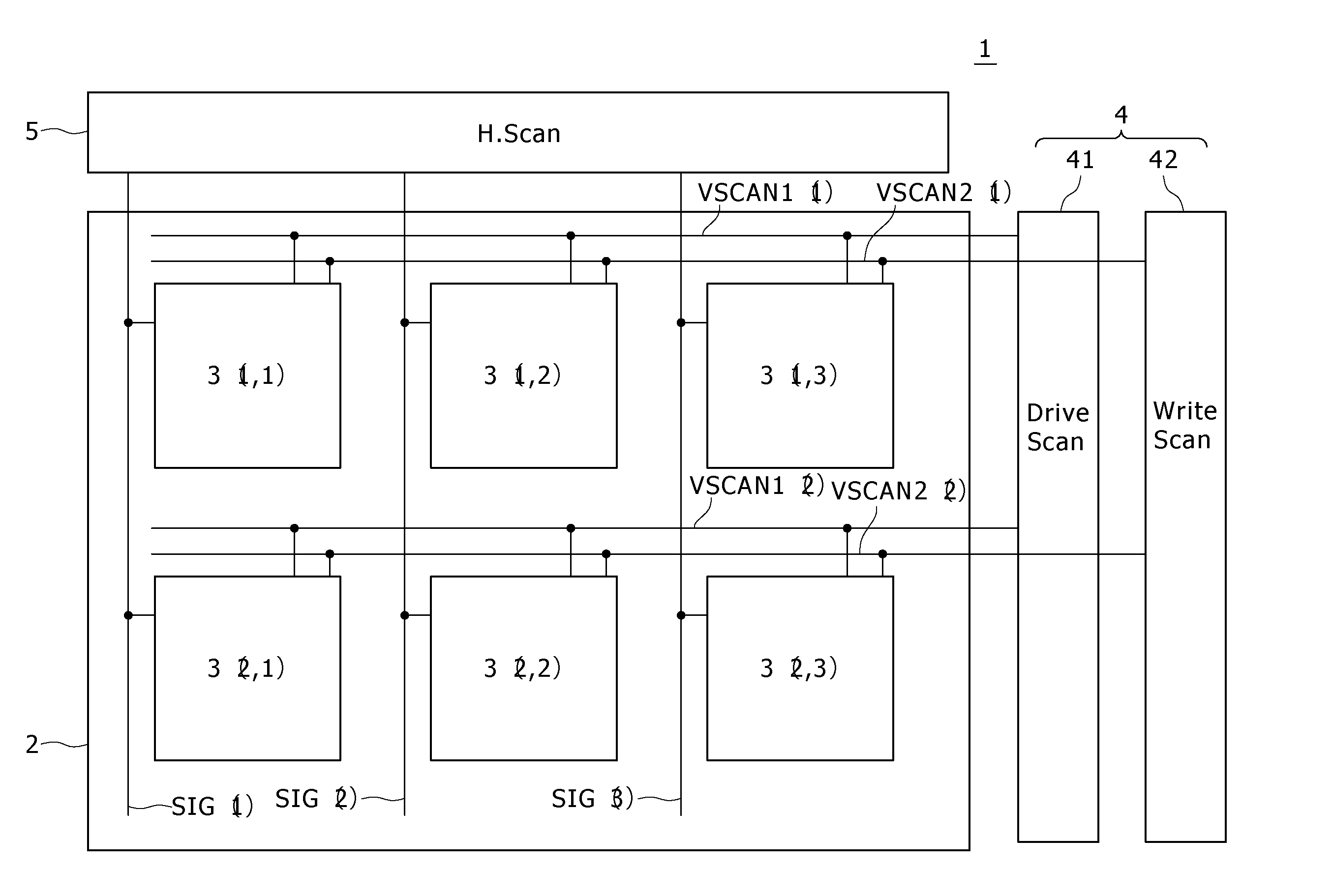
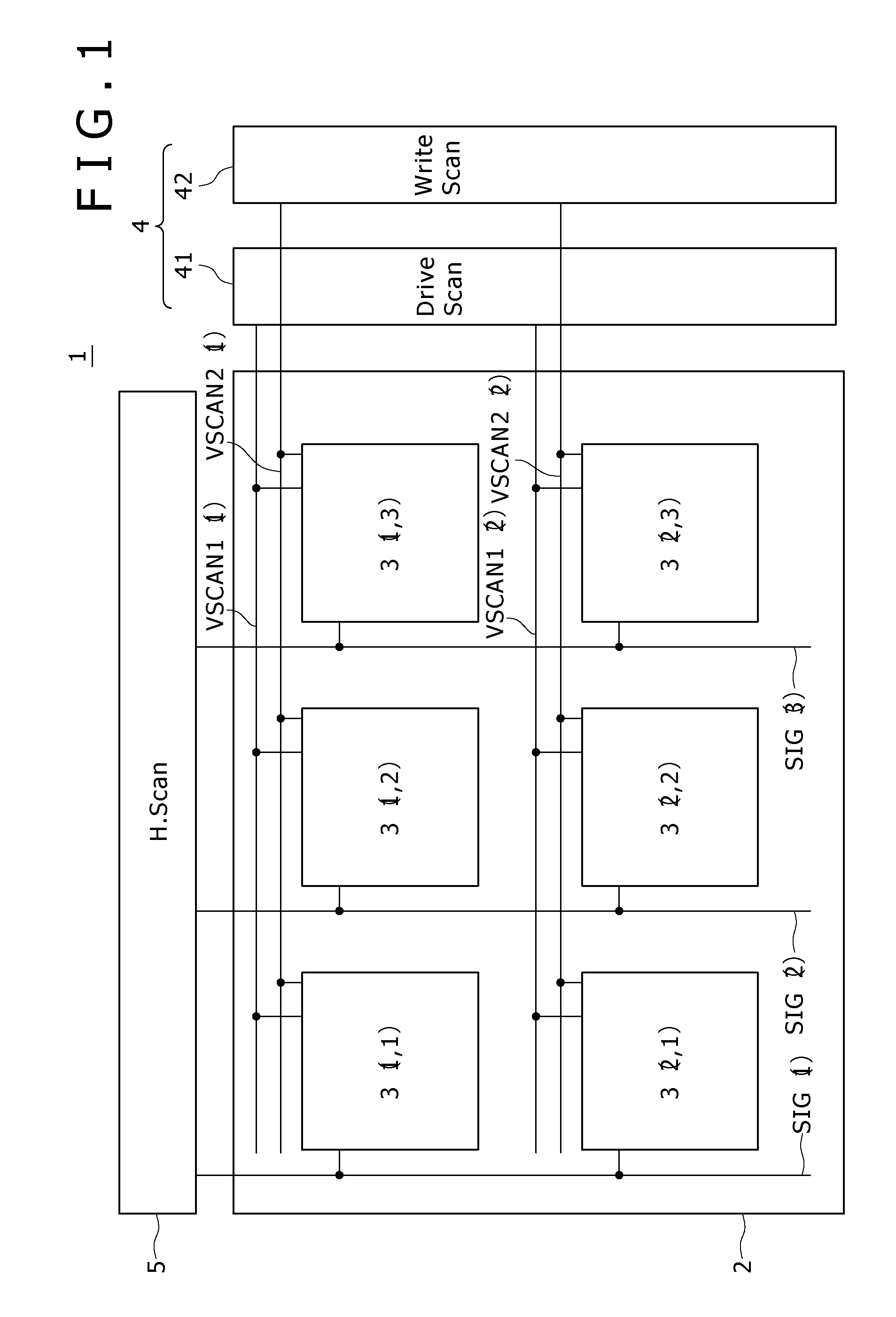
[0053]FIG. 1 is a diagram illustrating the major components of an organic EL display device according to an embodiment of the present invention.

[0054]An organic EL display device 1 illustrated in FIG. 1 includes a pixel array 2 and drive circuit. The pixel array 2 has a plurality of pixel circuits 3 (i,j) arranged in a matrix form. The drive circuit drives the pixel array 2 and includes a vertical drive circuit (V scanner) 4 and horizontal drive circuit (H scanner or H. Scan).

[0055]The plurality of V scanners 4 are provided depending on the configuration of the pixel circuits 3. Here, the V scanner 4 includes a horizontal pixel line drive circuit (DSCN) 41 and write signal scan circuit (WSCN) 42.

[0056]Reference symbol 3 (i,j) of the pixel circuits shown in FIG. 1 denotes ...


PUM


Abstract

A display device according to the present invention includes pixel units. Each of the pixel units is made up of N consecutive pixels. One of N (N≧3) colors including R (red), G (green) and B (blue) is assigned to each of the N pixels. Each of the N pixels includes a sampling transistor Ms, drive transistor Md, holding capacitor Cs and light-emitting element (organic light-emitting diode OLED). Of the N pixels, a specific color pixel that is susceptible to a dark dot (e.g., B) or that has the highest relative luminosity factor (e.g., G) has more sets of pixel circuit elements including the drive transistor Md, holding capacitor Cs and organic light-emitting diode OLED than other color pixels and has two or more sets thereof.

Description

TECHNICAL FIELD[0001]The present invention relates to a display device having a pixel array formed by regularly arranging a plurality of pixel units, each of which is adapted to display a single color and made up of N consecutive pixels of three or more colors. The present invention relates more particularly to a display device having, in each pixel, a pixel circuit formed by integrating a self-luminous light-emitting element adapted to emit light of a predetermined characteristic color by itself and part of a drive circuit of the same.BACKGROUND ART[0002]Some display devices use electro-optical elements whose brightness changes with change in voltage applied thereto or current flowing therethrough. For example, a liquid crystal display element is a typical example of an electro-optical element whose brightness changes with change in voltage applied thereto. An organic electro-luminescence element is a typical example of an electro-optical element whose brightness changes with chang...

Claims


Application Information

Patent Timeline
IPC IPC(8): G09G5/10G09G3/30
CPCG09G3/3233G09G2300/0452H01L27/3244H01L27/3211G09G2320/043H10K59/35H10K59/12G09G3/30G09G3/32
Inventor YAMAMOTO, TETSUROUCHINO, KATSUHIDE
Owner JOLED INC
Why Eureka
Try Eureka