Rod holder and minimally invasive spine surgery system using the same
a spine surgery and rod holder technology, applied in the field of rod holders, can solve the problems of pain to the person, poor satisfaction, and disease of the spine disk, and achieve the effects of convenient mounting, convenient manipulation, and easy insertion
- Summary
- Abstract
- Description
- Claims
- Application Information
AI Technical Summary
Benefits of technology
Problems solved by technology
Method used
Image
Examples
first embodiment
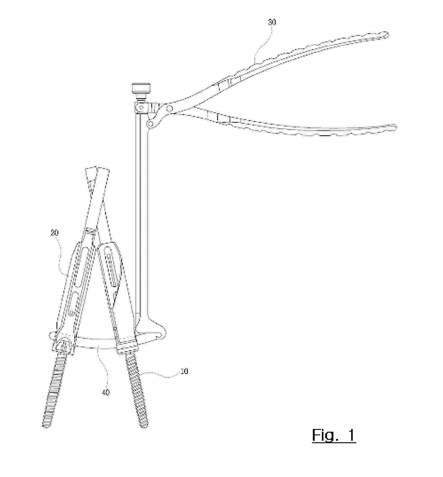
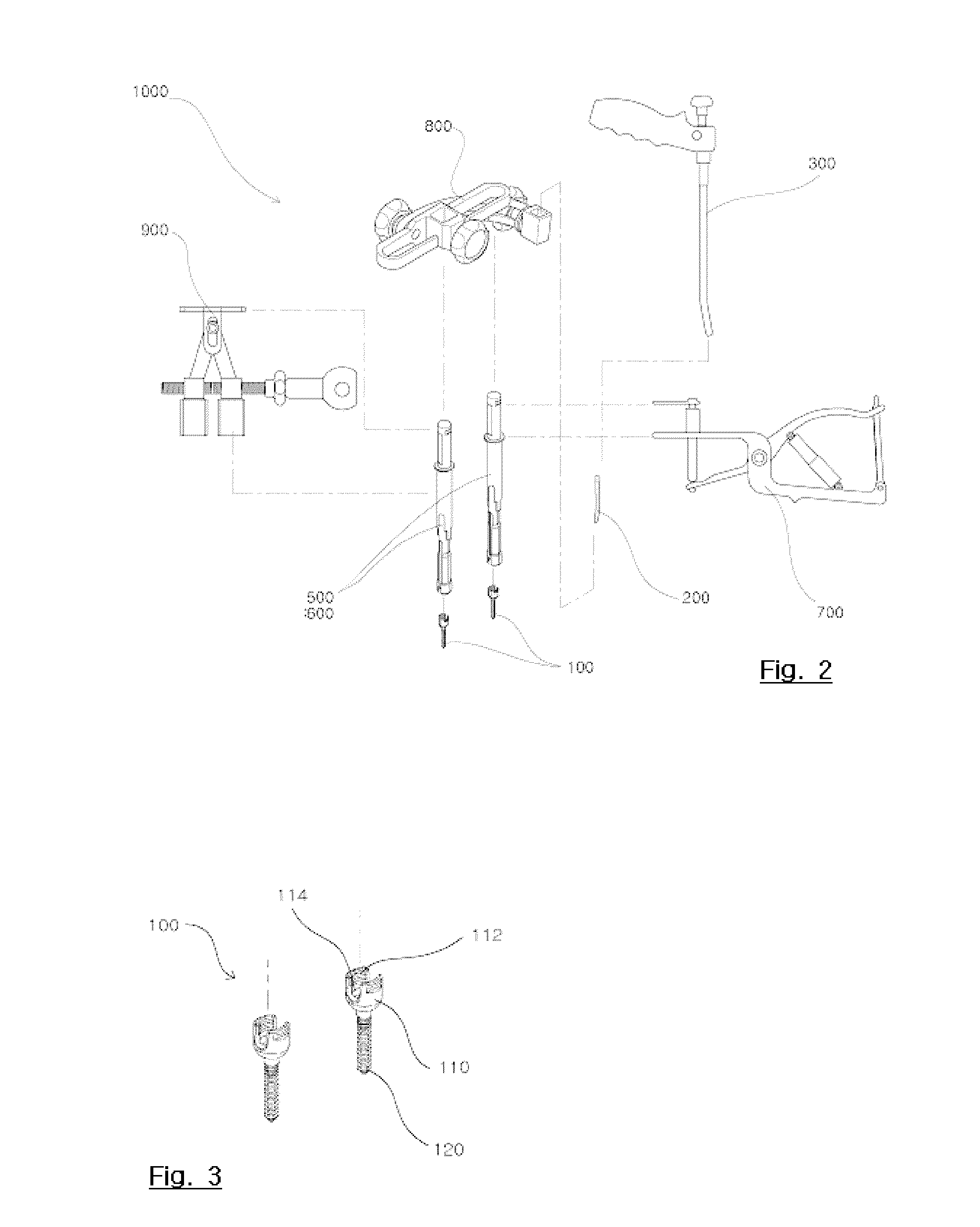
[0103]As shown in FIG. 17, the rod guide 500 of the first embodiment has a hollow cylindrical shape and a pair of cuts 510 are formed at a lower end of the rod guide in opposite directions such that the rod 200 may be inserted therein. Also, a flat fixed surface 530 is formed at an upper end of the rod guide to be perpendicular to the cut 510 such that the rod guide may be inserted in and fixed to a rod guide holder 800 explained later. The fixed surface 530 makes it possible to prevent the rod guide 500 from being rotated in the rod guide holder 800 explained later, so that it is possible to fundamentally prevent locations of the cuts 510 serving as a moving path of the rod from being changed. In addition, a pair of plane grooves 521, which can be gripped by a rod pusher 700 explained later, may be symmetrically formed on an upper end surface of the rod guide 500, wherein the groove and the cut 510 are formed on a straight line.
[0104]FIGS. 18 to 21 show the rod guide 600 of the sec...
second embodiment
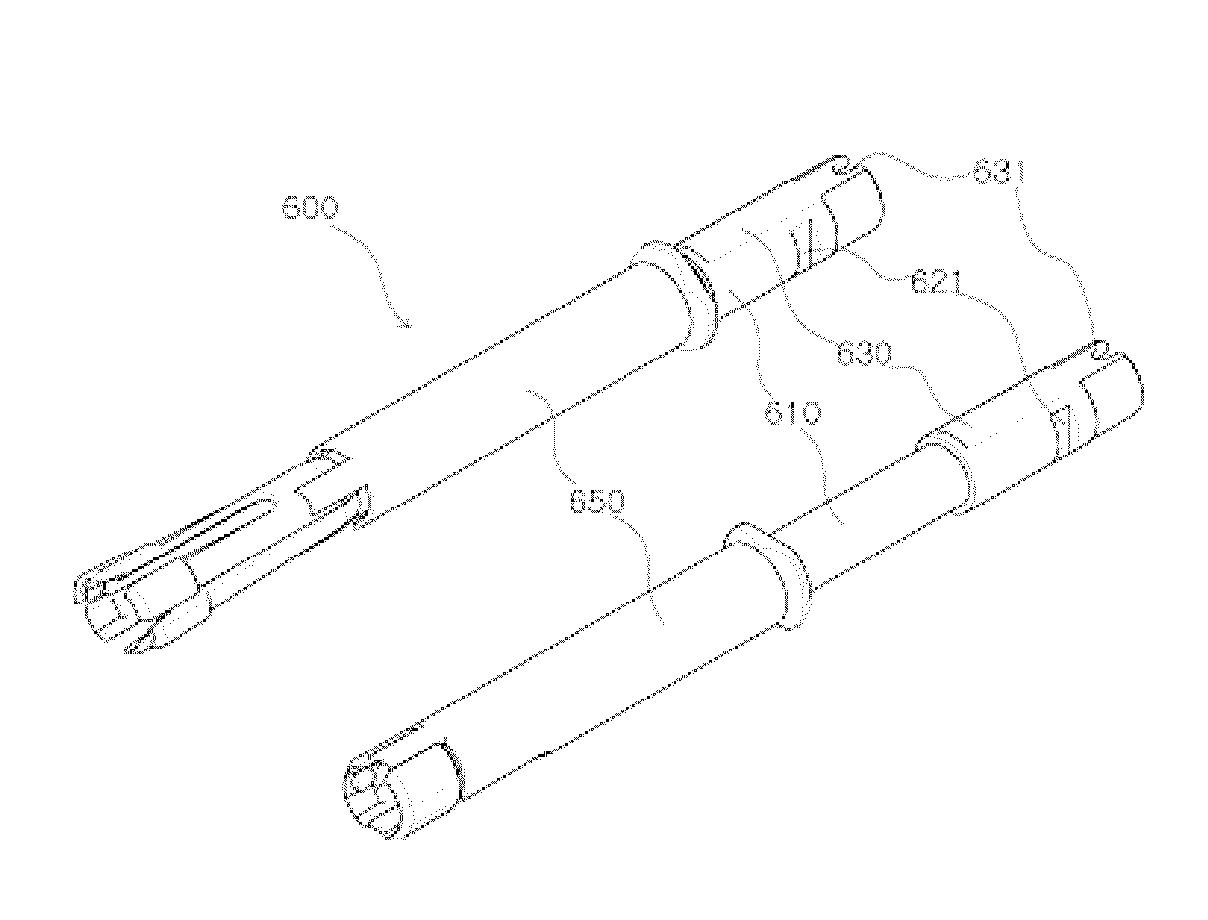
[0123]By using the rod pusher 700 as above, the outer sleeve 650 of the rod guide 600 of the second embodiment may be easily slid with a small power, and the rod pressing unit 657 may also compress the rod 200 more strongly with a small power.
[0124]Hereinafter, an operating mechanism of the rod guide 600 and the rod pusher 700 is explained.
[0125]First of all, the head portion 110 of the pedicle screw 100 is located at the gripping portion 617 of the inner body 610. At this time, the guide pin 653 of the outer sleeve 650 is located at the upper portion of the first vertical sliding guide unit 523a among the guide grooves 623 of the inner body 610. Due to the above, since the lower end of the outer sleeve 650 is located in the hollow tube 611 of the inner body 610, any pressing force is not yet transferred to the elastic arm 613 of the inner body 610, so that the gripping portion 617 does not still grip the pedicle screw 100. Also, in this state, one pair of cuts 655 of the outer slee...
PUM
 Abstract
Description
Claims
Application Information
 - R&D
- Intellectual Property
- Life Sciences
- Materials
- Tech Scout
- Unparalleled Data Quality
- Higher Quality Content
- 60% Fewer Hallucinations
Browse by: Latest US Patents, China's latest patents, Technical Efficacy Thesaurus, Application Domain, Technology Topic, Popular Technical Reports.
© 2025 PatSnap. All rights reserved.Legal|Privacy policy|Modern Slavery Act Transparency Statement|Sitemap|About US| Contact US: help@patsnap.com


