Vehicle controlling apparatus

Active Publication Date: 2011-03-31
TOYOTA JIDOSHA KK
View PDF2 Cites 26 Cited by
  • Summary
  • Abstract
  • Description
  • Claims
  • Application Information

AI Technical Summary

Benefits of technology

[0024]The vehicle controlling apparatus according to the present invention does not execute the vehicle body vibration-damping control using the information of the wheel speed on which the noise (high-frequency component) is superimposed or with deviation such that the drive system does not resonate. Also, the vehicle controlling apparatus adjusts the control amount of the vehicle body vibration-damping control in a direction to suppress a vibration-damping effect of the vehic

Problems solved by technology

However, when a high-frequency input enters the wheel from a road surface such as when the vehicle travels on a stone pavement, the high-frequency input is also transmitted to the drive system through the drive wheel and the drive system resonates by a high-frequency component of the road surface input and the drive system vibration, so that deviation occurs in a detected value of a wheel speed of the driving wheel.
Although the high-freq

Method used


Image

  • Vehicle controlling apparatus
  • Vehicle controlling apparatus
  • Vehicle controlling apparatus

Examples


embodiments

First Embodiment

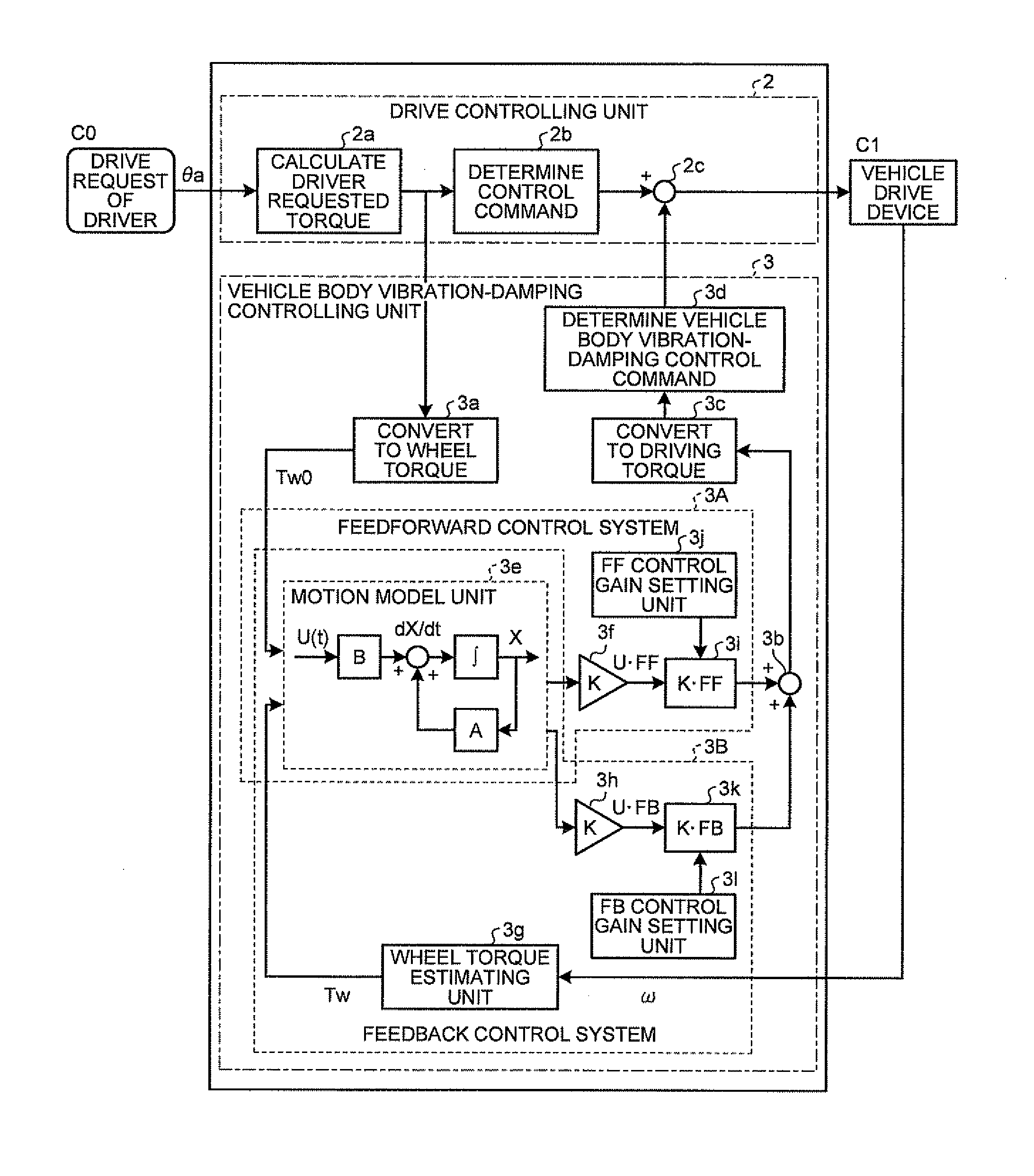
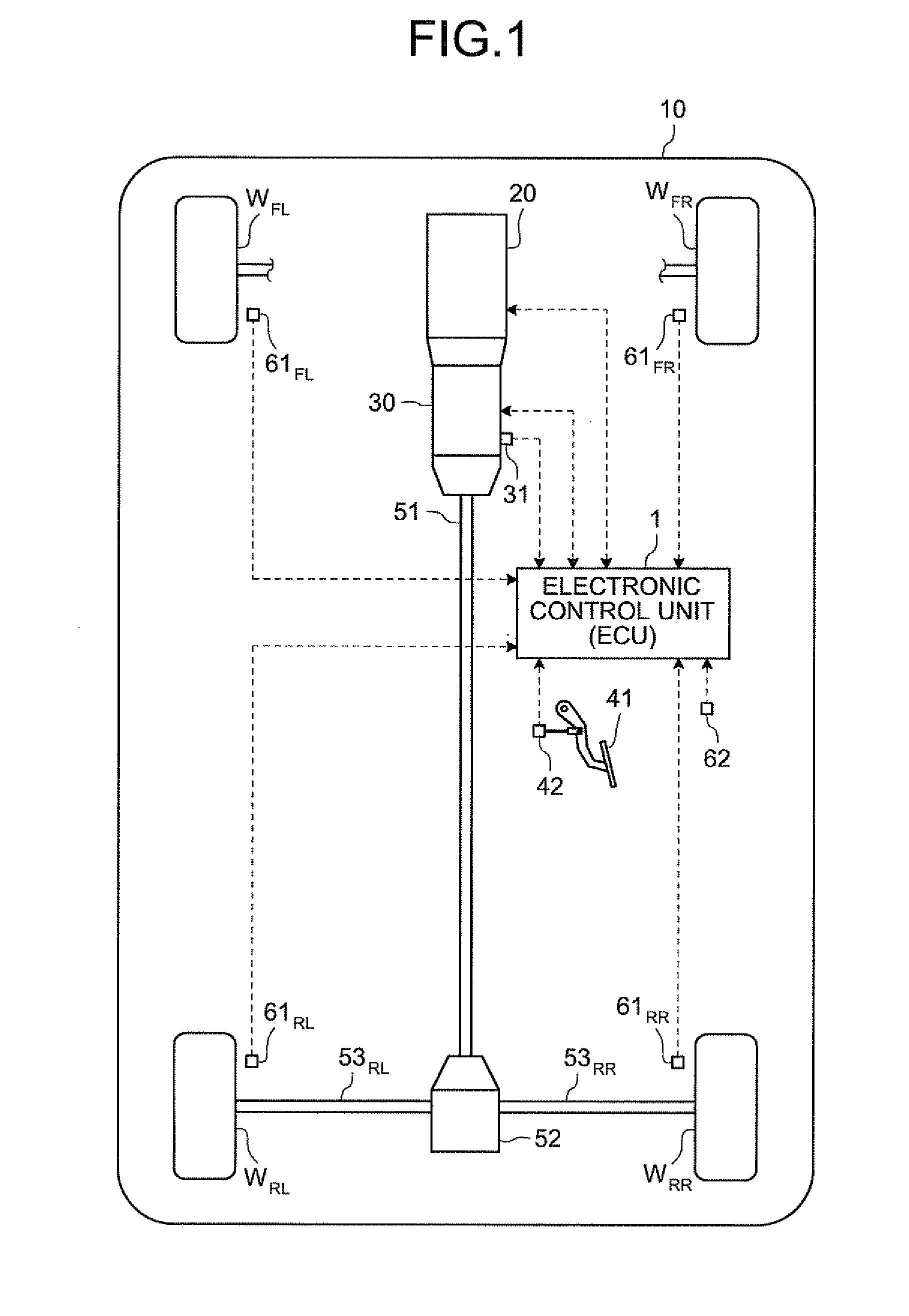
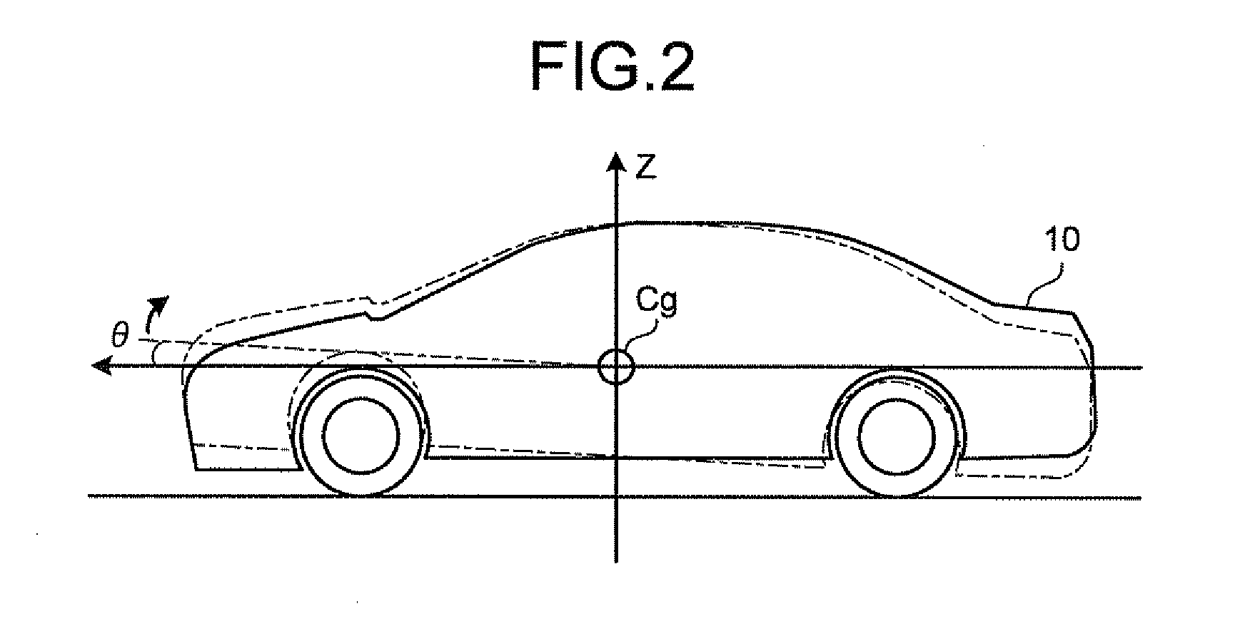
[0054]A first embodiment of the vehicle controlling apparatus according to the present invention is described with reference to FIGS. 1 to 8.

[0055]The vehicle controlling apparatus of the first embodiment is provided as a function of an electronic control unit (ECU) 1 illustrated in FIG. 1. The electronic control unit 1 is composed of a central processing unit (CPU) not illustrated, a read only memory (ROM) for storing a predetermined control program and the like in advance, a random access memory (RAM) for temporarily storing a calculation result of the CPU and a backup RAM for storing information provided in advance and the like.

[0056]First, an example of a vehicle 10 to which the vehicle controlling apparatus is applied is illustrated in FIG. 1. Herein, a front engine rear drive (FR) vehicle, which transmits an output (output torque) from a power source on a front side of the vehicle to driving wheels WRL and WRR on a rear side of the vehicle as wheel driving forc...

second embodiment

[0137]A second embodiment of the vehicle controlling apparatus according to the present invention is described with reference to FIGS. 9 to 10.

[0138]The vehicle controlling apparatus of the second embodiment is obtained by replacing the vehicle body vibration-damping control inhibiting means with vehicle body vibration-damping control amount adjusting means in the above-described vehicle controlling apparatus of the first embodiment or by providing the vehicle body vibration-damping control amount adjusting means together with the vehicle body vibration-damping control inhibiting means.

[0139]The vehicle body vibration-damping control amount adjusting means is for adjusting in a direction in which the vehicle body vibration-damping control is suppressed, that is to say, for decreasing a set value of the vehicle body vibration-damping control (set vehicle body vibration-damping control amount) in a direction to suppress a suppression effect of the sprung vibration by the vehicle body ...


PUM


Abstract

A vehicle controlling apparatus that performs vehicle body vibration-damping control to suppress vibration occurring in a vehicle body by changing wheel torque of driving wheels by controlling output torque of engine, wherein an electronic control unit is provided with a vehicle body vibration-damping control inhibiting unit that inhibits the vehicle body vibration-damping control such that a drive system of a vehicle, which transmits power of the engine, does not resonate with execution of the vehicle body vibration-damping control, or/and a vehicle body vibration-damping control adjusting unit that adjusts a control amount of the vehicle body vibration-damping control in a direction to suppress a vibration-damping suppression effect of the vehicle body vibration-damping control.

Description

TECHNICAL FIELD[0001]The present invention relates to a vehicle controlling apparatus for performing vehicle body vibration-damping control for suppressing vibration occurring in a vehicle body.BACKGROUND ART[0002]Technology referred to as the vehicle body vibration-damping control to suppress the vibration occurring in the vehicle body by using predetermined vehicle body vibration-damping suppressing means is conventionally known. For example, in the vehicle body vibration-damping control, pitching motion to increase or decrease driving torque of a driving wheel (hereinafter, referred to as “wheel torque”) to suppress the vibration by the wheel torque is generated in the vehicle body. Herein, the following Patent Document 1 discloses technology to correct an input command so as to suppress the vibration of the vehicle body by using a motion model, which is a mechanical model of vibration of a tire of the vehicle, vibration below a spring of the vehicle body in a suspension and vibr...

Claims


Application Information

Patent Timeline
IPC IPC(8): G06F19/00
CPCB60W10/06B60W10/10B60W30/20B60W50/0098B60W2710/105B60W2540/16B60W2550/147B60W2710/0666B60W2520/16B60W2552/35
Inventor OTSUKA, TAKAYUKI
Owner TOYOTA JIDOSHA KK
Why Eureka
Try Eureka