
Actuating apparatus for actuating at least one shift apparatus and method for the assembly and disassembly thereof

a technology of actuating apparatus and shift apparatus, which is applied in the direction of manufacturing tools, transportation and packaging, and manufacturing tools, can solve the problems that the complete activating mechanism is positioned inside the hollow shaft and cannot be realized with the known manual transmission, and achieves the effect of simple and safe assembly

Inactive Publication Date: 2011-04-07
ZF FRIEDRICHSHAFEN AG
View PDF49 Cites 0 Cited by
  • Summary
  • Abstract
  • Description
  • Claims
  • Application Information

AI Technical Summary

Benefits of technology

[0006]It is the task of this invention to propose an actuating apparatus, as well as a method, for the assembly and disassembly of the earlier described type, which enables especially simple and safe assembly and disassembly of the actuating apparatus.
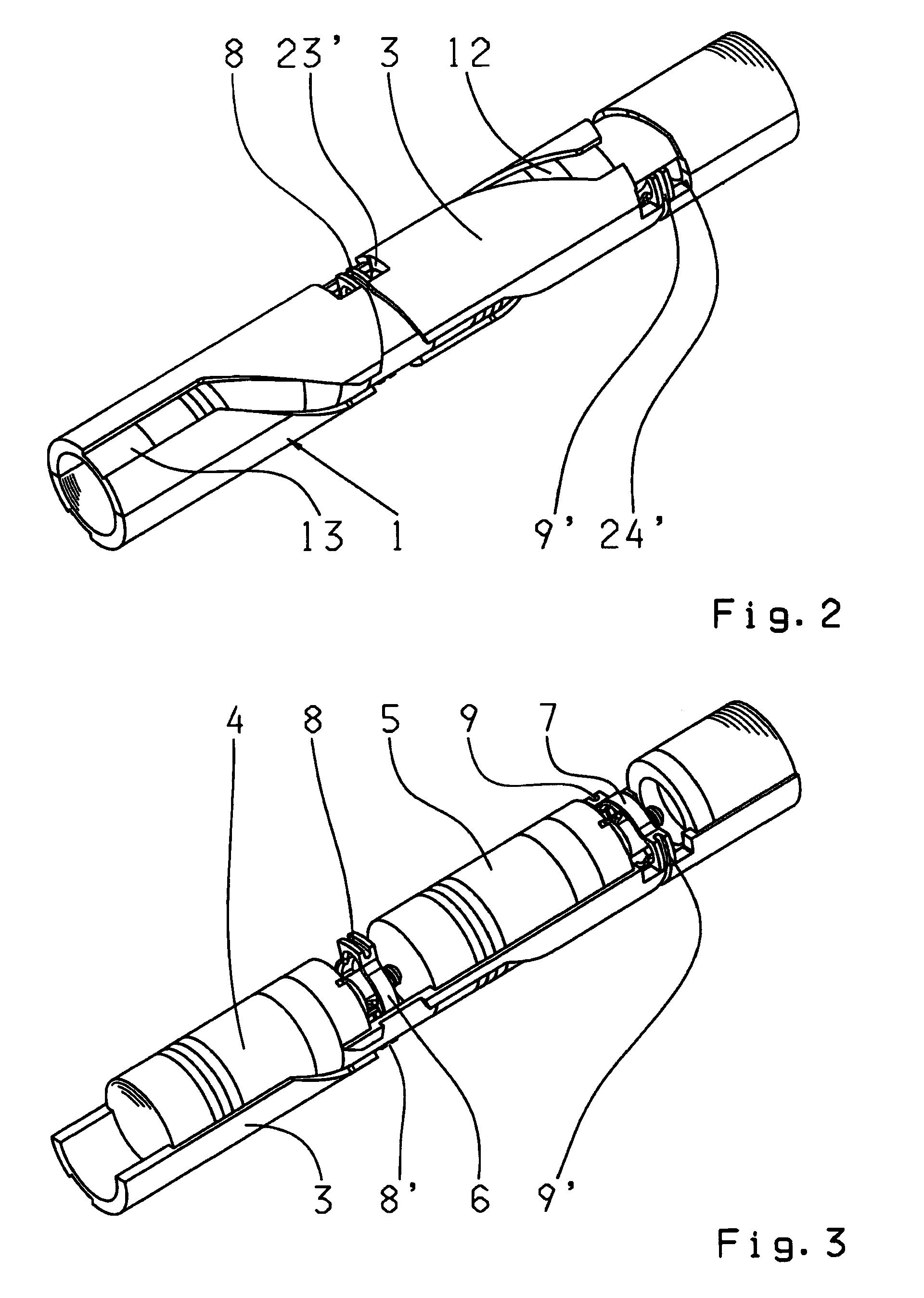
[0008]Thus, to realize an operational connection between the respective actuator and the assigned coupling element of the shifting mechanism, the actuator module of the proposed actuating apparatus can be inserted in a simple way into the hollow shaft, through which the assigned coupling elements are moved along the respective assembly guidance when the activated module is inserted. As long as the coupling elements are not in operational connection with the assigned actuator, the actuator module can be inserted into the hollow shaft. Thus, an assembly concept capable of volume production has been realized through the inventive and proposed actuating apparatus. Thus, and for instance, several linear actuators, including the required electronics and with the inductive rotating transformer, as well as additional accessories, can be combined in the actuator module and can be assembled in one step. Due to the small amount of external interfaces of the actuator module, a high level of quality assurance and an especially low retrofit percentage can be ensured.
[0011]In an offset accommodation area configuration in the circumferential direction for the different spindle nuts, the advantage arises that the associated coupling elements on the hollow shaft are also positioned in an offset. Since the hollow shaft has the corresponding oblong holes, or similar, to realize the axial movement of the coupling elements, also the oblong holes are positioned in an offset across the circumferential area of the hollow shaft which is advantageous in regard to the stiffness of the hollow shaft. Hereby, an even deflection of the shaft, in relationship to the rotation angle of the shaft, is realized.
[0017]To disconnect the operational connection of the actuator module, during the disassembly or retrofit, between the coupling elements and the respective spindle nuts, it can be provided that for each movement area of the spindle nut a respective extraction section, opposite of the insertion section, is available for the extraction of the respective coupling element into the neighboring assembly guide, to terminate the operational connection. Preferably, the extraction section which is opposite from the insertion section, is enlarged in regard to its dimensions, to comfortably extract the coupling element from the accommodation area, independent of the axial position of the spindle nut.

Problems solved by technology

Therefore, a modular construction, where the complete activating mechanism is positioned inside of the hollow shaft, cannot be realized with the known manual transmission.

Method used


Image

  • Actuating apparatus for actuating at least one shift apparatus and method for the assembly and disassembly thereof
  • Actuating apparatus for actuating at least one shift apparatus and method for the assembly and disassembly thereof
  • Actuating apparatus for actuating at least one shift apparatus and method for the assembly and disassembly thereof

Examples


Embodiment Construction

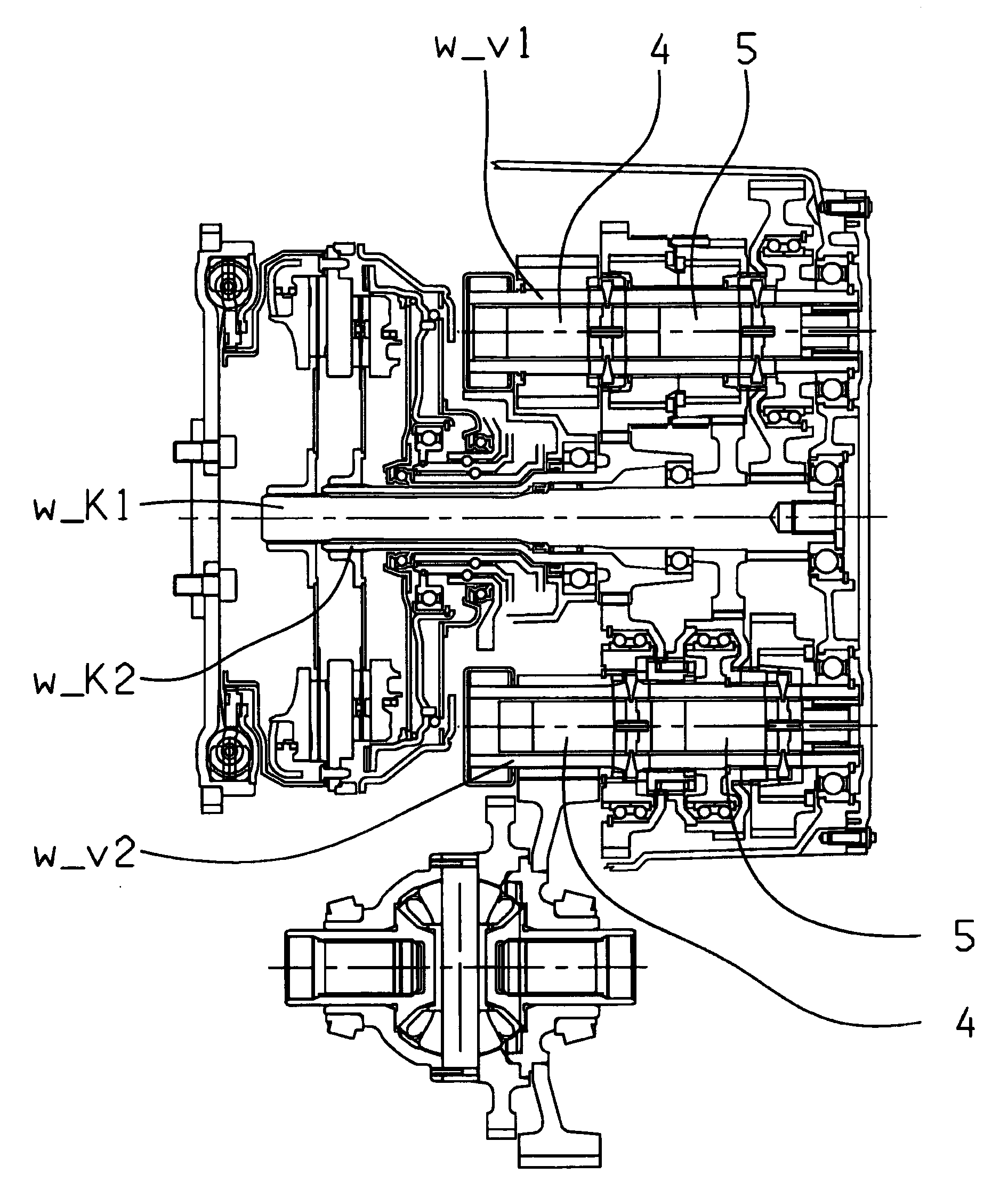
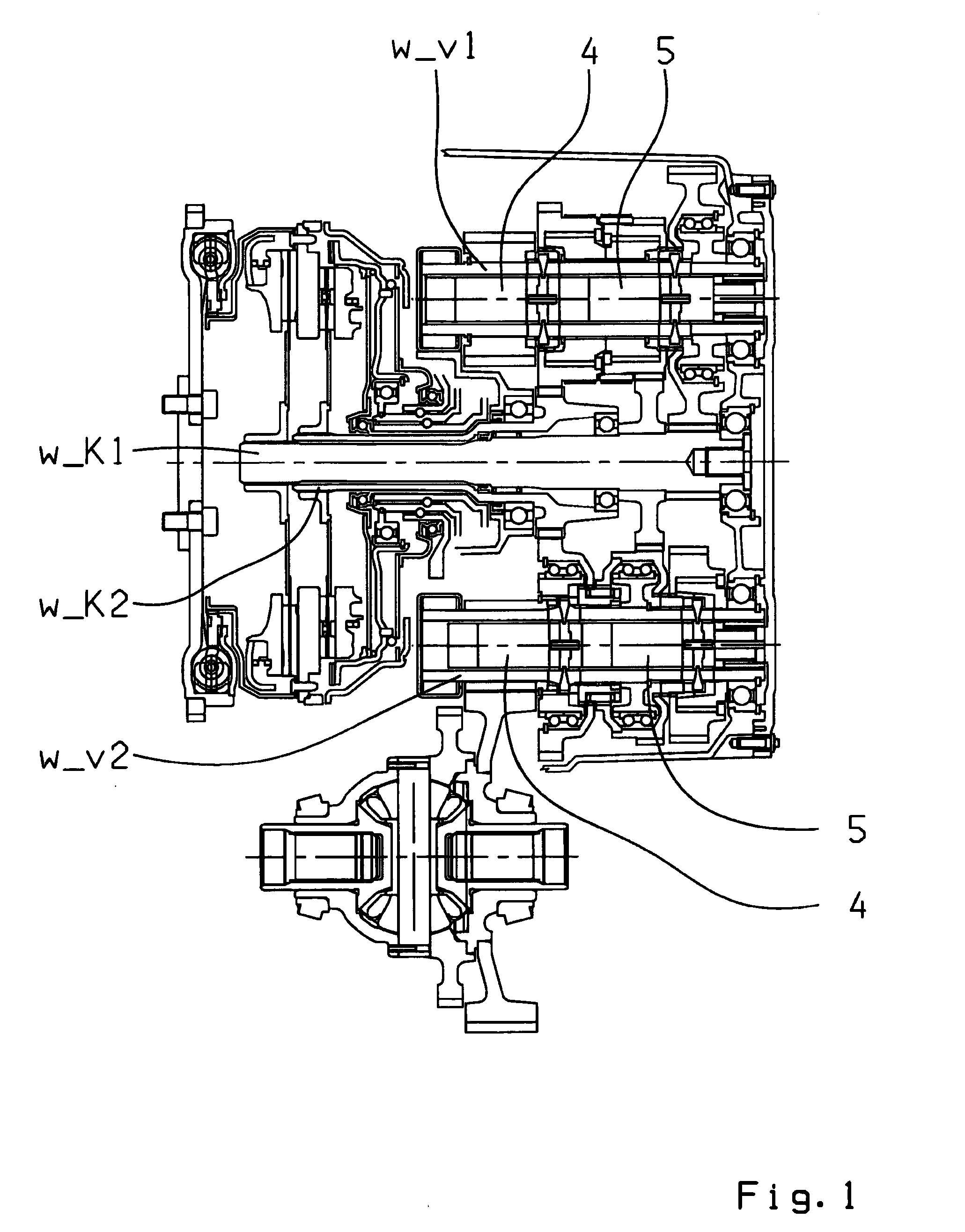
[0028]FIG. 1 presents an exemplary, possible application area for a proposed actuating apparatus, in accordance with the invention, for the actuation of at least one shift mechanism or shift elements of a multi-gear double clutch transmission which is designed as a countershaft transmission and shown in the sectional view.

[0029]The double clutch transmission comprises two clutches, with its inputs connected to a drive shaft. Also, a torsion vibration damper is positioned on the drive shaft. The outputs of the clutches are each connected with one of two coaxially positioned transmission input shafts w_K1, w_K2. The first transmission input shaft w_K1 is designed as a solid shaft, and the second transmission input shaft w_K2 is designed as a hollow shaft. In addition, two layshafts w_v1 and w_v2 are provided which are positioned axially parallel to each other. Several idle gears are positioned on each layshaft w_v1, w_v2 and which mesh with fixed gear wheels on the transmission input ...


PUM

PropertyMeasurementUnit
Timeaaaaaaaaaa
Angleaaaaaaaaaa
Angleaaaaaaaaaa

Abstract

An actuating apparatus for actuating a shifting mechanism in a transmission to shift a gear wheel on a hollow shaft with an actuator module that is at least partially positioned within the hollow shaft and which comprises an actuator which can be connected with a coupling element of the shift mechanism which radially, inwardly extends into the inner diameter of the hollow shaft. The enclosure of the actuator module has at least an axially extending assembly passageway which guides the coupling element, during axial insertion of the actuator module into the hollow shaft. A method for the assembly and disassembly of an actuator module, with at least one actuator of an actuating apparatus for inside actuation of a shift mechanism on the hollow shaft. The actuator module is axially inserted into the hollow shaft and rotated via an assembly guide.

Description

[0001]This application is a National Stage completion of PCT / EP2009 / 052013 filed Feb. 20, 2009, which claims priority from German patent application serial no. 10 2008 000 638.6 filed Mar. 13, 2008.FIELD OF THE INVENTION[0002]The present invention concerns an actuating apparatus for actuating at least one shift apparatus of a transmission. Also, the invention concerns a method of the assembly and disassembly of an actuating apparatus.BACKGROUND OF THE INVENTION[0003]It is known in the art of automotive engineering that shift mechanisms, or shift elements, for instance in countershaft transmissions are radial actuated externally by means of the shift forks or shift levers. For example, transmissions are known from DE 43 25 964 and DE 103 02 502 A1 where the shift mechanisms or shift elements each comprise an axially movable sliding sleeve. The sliding sleeves are hydraulically controlled. For that purpose, appropriate cooling oil supply channels are positioned in the shaft which has ...

Claims


Application Information

Patent Timeline
IPC IPC(8): F16H59/02B23P11/00
CPCF16C33/80Y10T74/20177Y10T29/49826F16H3/006F16H61/32F16H63/30F16H2003/0931F16H2063/3093F16H2061/2884Y10T74/19251Y10T74/19274
Inventor REISCH, MATTHIASGUMPOLSTBERGER, GERHARD
Owner ZF FRIEDRICHSHAFEN AG
Learn More