MRI compatible implantable lead

a technology of implantable leads and compatible leads, which is applied in the direction of overhead lines/cables, transformers/inductance coils/windings/connections, etc., can solve the problems of nerve stimulation in the tissue, erroneous diagnosis or therapy delivery, and unwanted tissue heating, so as to facilitate maintenance of stable and small dc resistance

Active Publication Date: 2011-04-07
PACESETTER INC
View PDF20 Cites 53 Cited by
  • Summary
  • Abstract
  • Description
  • Claims
  • Application Information

AI Technical Summary

Benefits of technology

[0014]At least certain embodiments of the present invention add one or more electrical circuit pathways to interconnect the turns or filars in the bare coil or cable segments. The additional circuit pathways facilitate mainte...

Problems solved by technology

When exposed to electromagnetic fields, such as for example those present in magnetic resonance imaging (“MRI”) systems, these leads may sustain undesired currents and or voltages that interact with the surrounding blood and tissue, potentially resulting in unwanted tissue heating, nerve stimulation or other negative effects resulting in erroneous diagnosis or therapy delivery.
These currents may induce heating or cause nerve stimulation in the tissue surrounding the device either directly or by creating current pathways through the tissue that interacts with the electrodes.
The conductive paths provided by coiled wires can sustain unwanted curr...

Method used


Image

  • MRI compatible implantable lead
  • MRI compatible implantable lead
  • MRI compatible implantable lead

Examples


Embodiment Construction

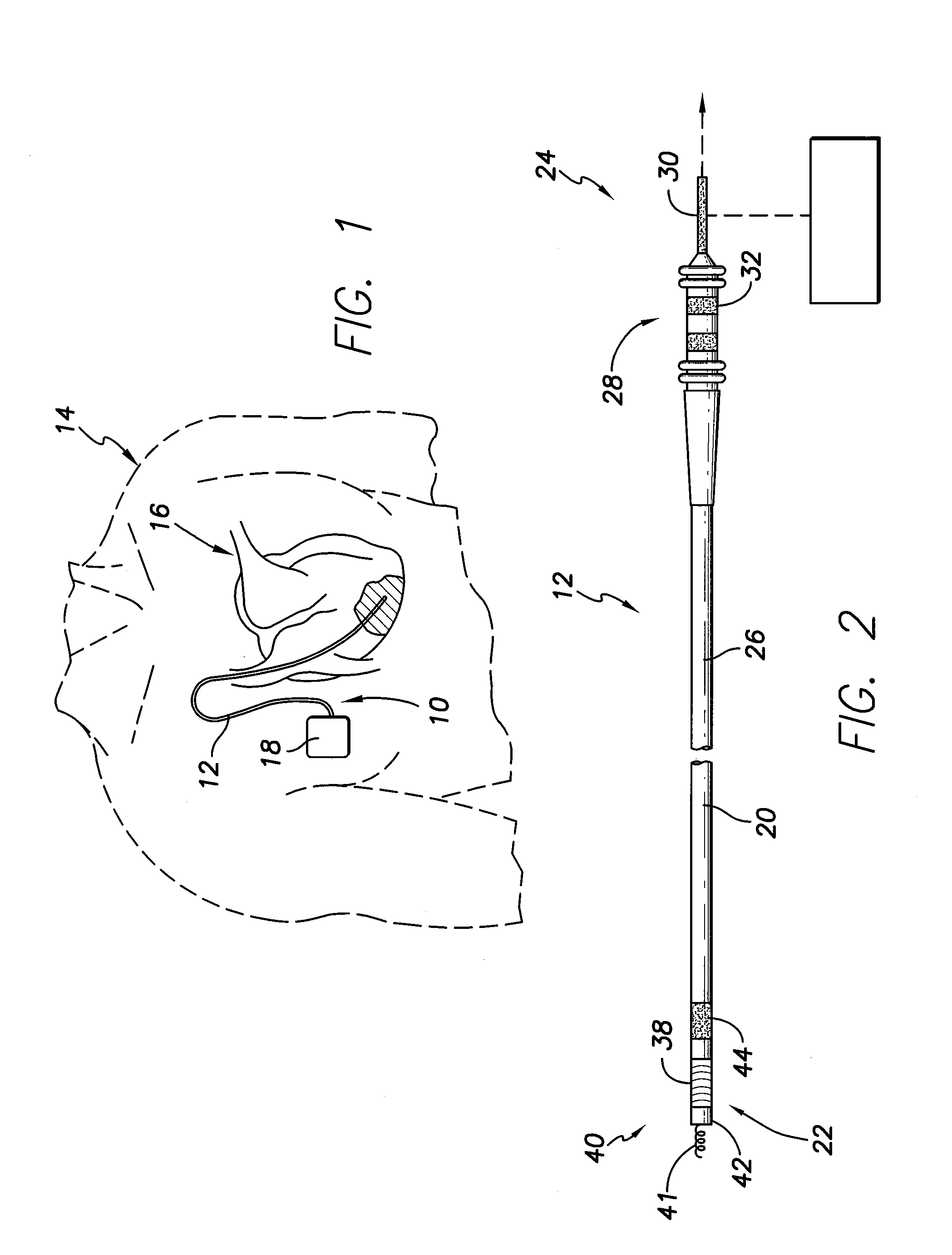
[0035]FIG. 1 illustrates an implantable medical system 10 including an implantable lead 12 formed in accordance with an exemplary embodiment. FIG. 1 depicts a chest cavity 14 in phantom, and a heart 16 within the chest cavity 14. The medical system 10 includes an implantable medical device (IMD) 18 and the lead 12, which are both implanted in the chest cavity 14. Optionally, the medical device 18 may be implanted elsewhere, such as in the patient's abdomen, neck, pelvis regions, etc. In the illustrated embodiment, the lead 12 is a pacing and sensing lead. However, other types of leads may be used in alternative embodiments, such as neuromodulation leads, defibrillation leads, patient monitoring leads and the like. Although the following embodiments are described principally in the context of pacemaker / defibrillator unit capable of sensing and / or pacing pulse delivery, the medical system 10 may be applied to other IMD structures. As further examples, embodiments may be implemented in...


PUM


Abstract

An implantable lead is provided that includes a lead body configured to be implanted in a patient. The lead body has a distal end and a proximal end, and a lumen extending between the distal and proximal ends and includes a connector assembly provided at the proximal end of the lead body. The connector assembly is configured to connect to an implantable medical device and includes an electrode provided proximate to the distal end of the lead body with the electrode configured to at least one of deliver stimulating pulses and sense electrical activity. A multi-layer coil is located within the lumen and extends at least partially along a length of the lead body. The coil includes a first winding formed with multiple winding turns, the winding turns being segmented in an alternating pattern of insulated segments and non-insulated segments along the length of the lead body. The multi-layer coil further includes a winding turn connective layer extending along and interconnecting the winding turns within at least one of the non-insulated segments. The multi-layer coil further includes a first winding formed with multiple winding turns, the winding turns being segmented into an alternating pattern of insulated segments and non-insulated segments along a length of the winding with a winding turn connective layer extending along and interconnecting the winding turns within at least one of the non-insulated segments.

Description

CROSS REFERENCE TO RELATED APPLICATIONS[0001]This application claims the benefit of U.S. Provisional Application Ser. No. 61 / 249,184, filed Oct. 6, 2009.FIELD OF THE INVENTION[0002]Embodiments of the present invention generally relate to MRI compatible leads, and more particularly to MRI compatible leads that utilize a zebra coil configuration.BACKGROUND OF THE INVENTION[0003]Numerous medical devices exist today, including but not limited to electrocardiographs (“ECGs”), electroencephalographs (“EEGs”), squid magnetometers, implantable pacemakers, implantable cardioverter-defibrillators (“ICDs”), neurostimulators, electrophysiology (“EP”) mapping and radio frequency (“RF”) ablation systems, and the like (hereafter generally “implantable medical devices” or “IMDs”. IMDs commonly employ one or more conductive leads that either receive or deliver voltage, current or other electromagnetic pulses from or to an organ or its surrounding tissue for diagnostic or therapeutic purposes. The le...

Claims


Application Information

Patent Timeline
IPC IPC(8): H05K9/00H01F27/30
CPCA61N2001/086A61N1/056A61N1/086
Inventor ZHAO, YONG D.HILL, ROLFVIOHL, INGMARCHOLETTE, MARTIN
Owner PACESETTER INC
Why Eureka
Try Eureka