Membrane filtering device managing system and membrane filtering device for use therein, and membrane filtering device managing method

a filtering device and management system technology, applied in the direction of membranes, separation processes, instruments, etc., can solve the problems of insufficient management precision, large labor requirements in specifying work, and inability to say that sufficient optimization is carried out, so as to achieve suitable maintenance and higher precision

Active Publication Date: 2011-04-07
NITTO DENKO CORP
View PDF15 Cites 10 Cited by
  • Summary
  • Abstract
  • Description
  • Claims
  • Application Information

AI Technical Summary

Benefits of technology

[0046]According to the present invention, the cause of change occurring in the membrane filtering device can be specified more definitely, and a suitable maintenance can be carried out in accordance with the cause, so that the membrane filtering device can be managed with a higher precision.

Problems solved by technology

However, when the management of processing characteristics is carried out train by train as described above, it is difficult to specify the location of an inconvenience when the inconvenience occurs in the membrane element or the connecting section of only a part of the membrane filtering devices among the numerous membrane filtering devices that are held by a train, thereby raising a problem in that a lot of labor will be required in the specifying work.
However, in the current situation, the optimization is carried out only based on the term of use, so that it is not possible to say that a sufficient optimization is carried out.
However, even in a case in which the management is carried out based on only the data stored in advance in such a wireless tag, the state of each membrane element sometimes changes time by time, so that it is not possible to say that the precision of management is sufficient.

Method used


Image

  • Membrane filtering device managing system and membrane filtering device for use therein, and membrane filtering device managing method
  • Membrane filtering device managing system and membrane filtering device for use therein, and membrane filtering device managing method
  • Membrane filtering device managing system and membrane filtering device for use therein, and membrane filtering device managing method

Examples


Embodiment Construction

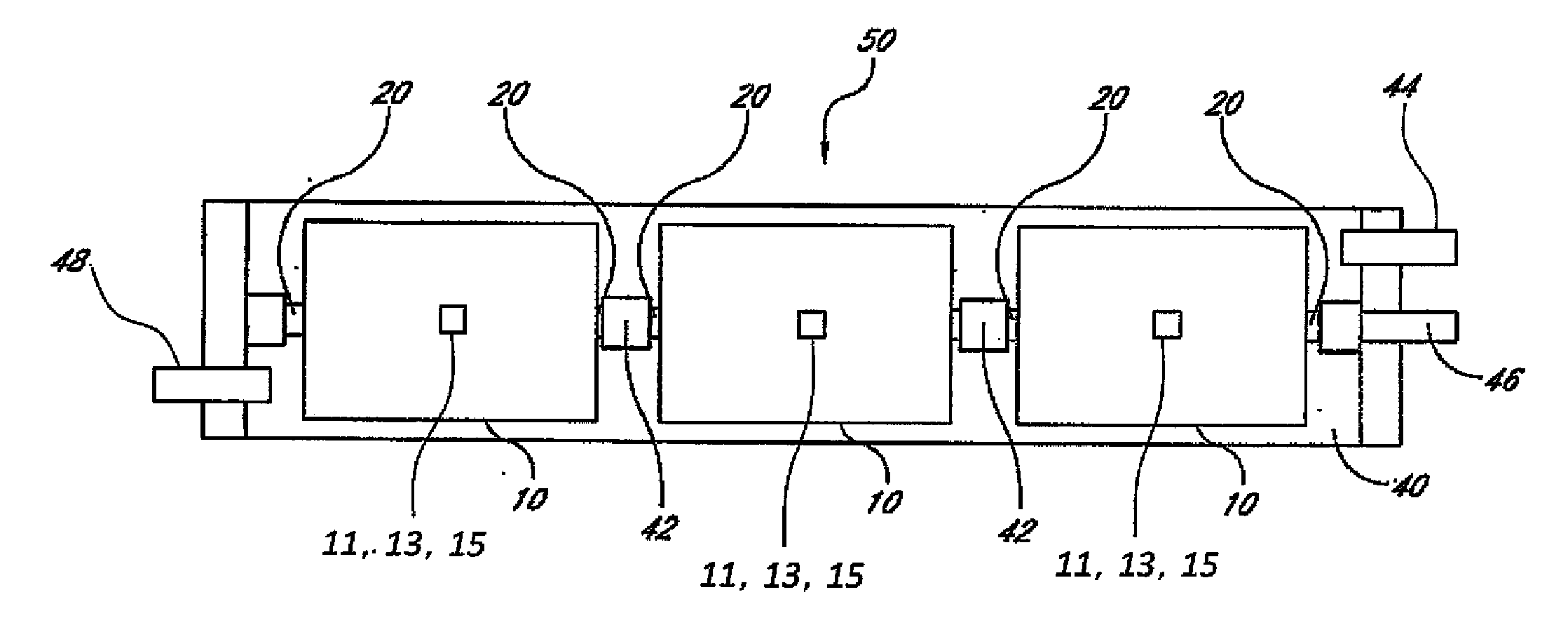
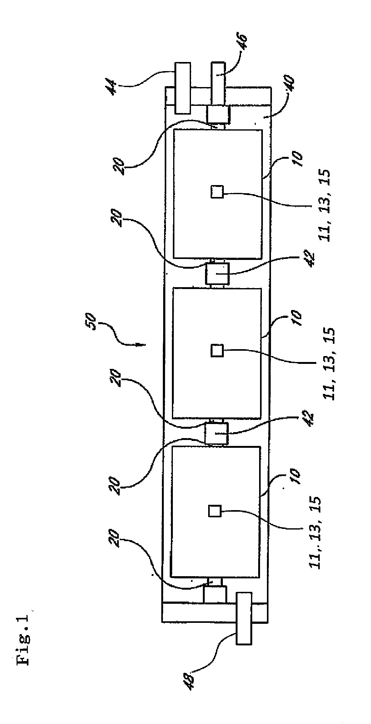
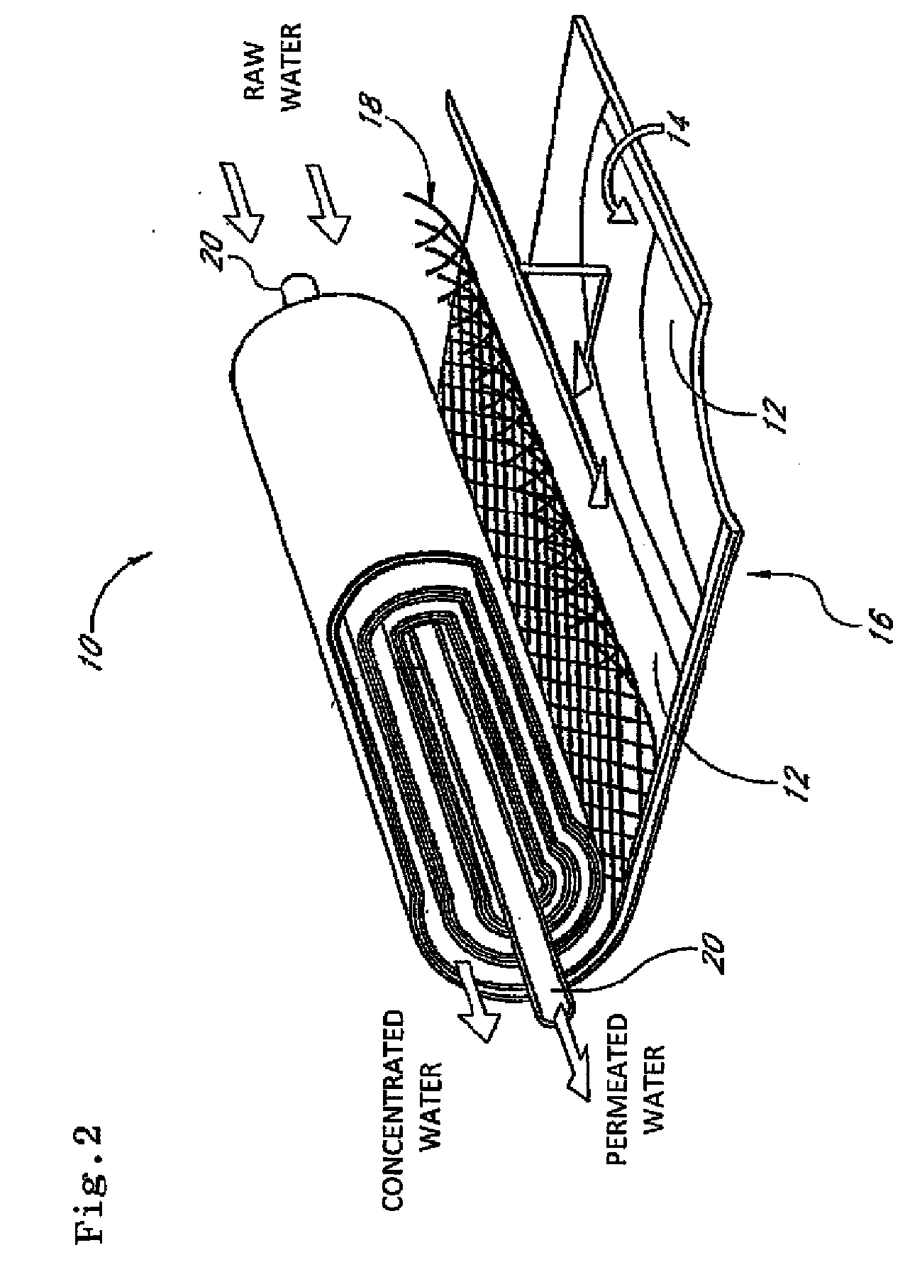
[0054]FIG. 1 is a schematic cross-sectional view illustrating one example of a membrane filtering device 50 according to one embodiment of the present invention. FIG. 2 is a perspective view illustrating an internal configuration of the membrane element 10 of FIG. 1. This membrane filtering device 50 is constructed by arranging a plurality of membrane elements 10 in a line within a pressure-resistant vessel 40.

[0055]The pressure-resistant vessel 40 includes a tubular body made of resin, and is formed, for example, of FRP (Fiberglass Reinforced Plastics). The plurality of membrane elements 10 are disposed and arranged along the axial line direction within this pressure-resistant vessel 40. A raw water flow inlet 48 through which a raw water (raw liquid) such as waste water or sea water flows in is formed at one end of the pressure-resistant vessel 40, and the raw water that flows in through the raw water flow inlet 48 at a predetermined pressure is filtered by a plurality of membrane...


PUM

PropertyMeasurementUnit
electric conductivityaaaaaaaaaa
pressureaaaaaaaaaa
fouling degreeaaaaaaaaaa

Abstract

Provided are a membrane filtering device managing system by which the membrane filtering device can be managed with a better precision and membrane filtering device for use therein, as well as to a membrane filtering device managing method. At least two sensors of an electric conductivity sensor 11, a flow rate sensor 13, and a pressure sensor 15 are provided in at least two membrane elements 10 provided in a membrane filtering device 50. A managing device 200 obtains data from the at least two sensor, and compares the data with comparison data that represents a correlative relationship between a position along the axial line direction in the membrane filtering device 50 and a standard value obtained from the at least two sensor. Accordingly, it is possible to specify the cause of change occurring in the membrane filtering device 50 more definitely, and to carried out a suitable maintenance in accordance with the cause, so that the membrane filtering device 50 can be managed with a higher precision.

Description

TECHNICAL FIELD[0001]The present invention relates to a membrane filtering device managing system for managing a membrane filtering device that is formed by disposing and arranging a plurality of membrane elements along an axial line direction within a tubular pressure-resistant vessel and generates a permeated liquid by filtering a raw liquid with the above membrane elements and membrane filtering device for use therein, as well as to a membrane filtering device managing method.BACKGROUND ART[0002]A membrane filtering device is known which is constructed in such a manner that a plurality of membrane elements are disposed on a straight line, and the above core tubes of adjacent membrane elements are connected with an interconnector (connecting section). The plurality of membrane elements that are connected in this manner are housed, for example, in a pressure-resistant vessel formed of resin, and are treated as one membrane filtering device (for example, refer to Patent Document 1)....

Claims


Application Information

Patent Timeline
Patent Type & Authority Applications(United States)
IPC IPC(8): B01D65/00B01D63/12
CPCB01D61/025B01D61/12C02F2209/40C02F2209/05C02F2209/03B01D63/106B01D63/12B01D2311/04B01D2311/16B01D2311/243C02F1/44C02F1/441C02F1/444C02F2103/08C02F2209/006B01D2311/246B01D2311/14Y02A20/131
Inventor KONISHI, TAKAHISAIKEYAMA, NORIOMARUYAMA, KOUJIFUJIWARA, YUKIOOOTANI, AKIRAKOUNO, TOSHIKI
Owner NITTO DENKO CORP
Why Eureka
Try Eureka