Fuel cell stack

Inactive Publication Date: 2020-04-23
HONDA MOTOR CO LTD
View PDF4 Cites 5 Cited by
  • Summary
  • Abstract
  • Description
  • Claims
  • Application Information

AI Technical Summary

Benefits of technology

The present invention provides a fuel cell stack with a simple structure that reduces production cost and prevents lateral displacement among power generation cells. The fuel cell stack includes a positioning structure and an engaging part, where the coupling bar with an insulating resin layer prevents lateral displacement among power generation cells and maintains insulation between the coupling bar and the stack body. Additionally, the engaging part engages with the stack body for power generation cell connection, reducing the size of the case and eliminating the need for an insulating structure around the power generation cells.

Problems solved by technology

In the fuel cell stack disclosed in the specification of U.S. Patent Application Publication No. 2016 / 0072145, since the insulating resin material is provided in the outer marginal portion of each separator, the production cost is increased.
However, increase in the size of the clearance may cause various disadvantages.

Method used


Image

  • Fuel cell stack
  • Fuel cell stack
  • Fuel cell stack

Examples


first modified embodiment

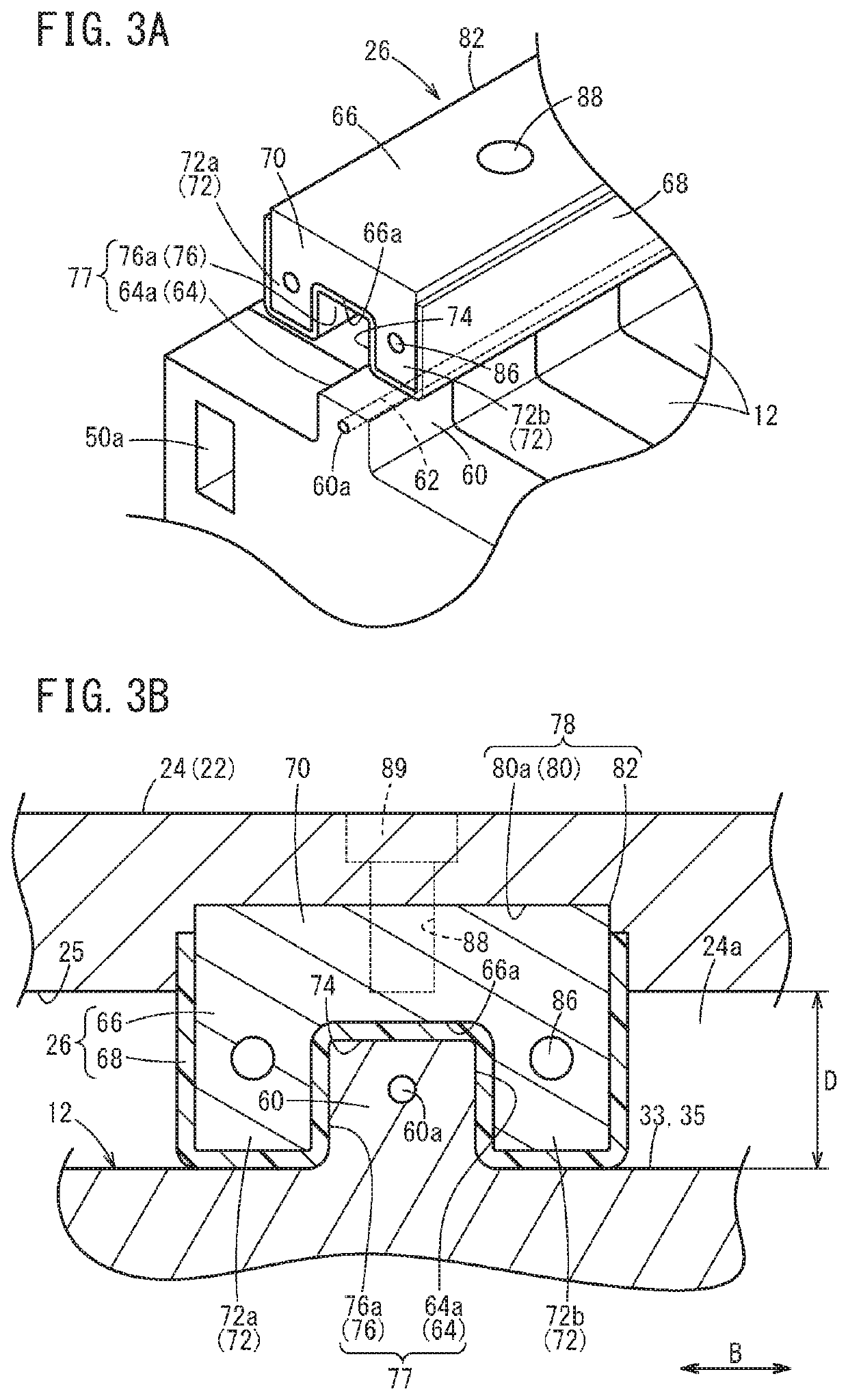
[0065]Further, as shown in FIG. 4A, a coupling bar 26 and a case 22 is different from the above described embodiment in respect of positioning structure 78A for fixing the coupling bar 26 and the case 22 with respect to each other. Specifically, the coupling bar 26 includes a positioning protrusion (ridge) 90 on a side of the proximal part 70 closer to the storage body 24. The positioning protrusion 90 protrudes toward the storage body 24. Further, the insulating resin layer 68 of the coupling bar 26 provided on the main body 66 covers the entire side surfaces of the proximal part 70, in addition to the pair of extensions 72.

[0066]On the other hand, the storage body 24 (case 22) has inside the storage body 24 an expansion 92 expanded slightly, and a positioned recess 94 for insertion of the positioning protrusion 90 is provided at the center of the expansion 92 in the width direction. The positioning protrusion 90 is inserted into the positioned recess 94. In this state, the positi...

third modified embodiment

[0068]As shown in FIG. 4C, a coupling bar 26 and a power generation cell 12 are different from the above described embodiment, and the first and second modified embodiments, in respect of engagement structure 77A for engagement of the coupling bar 26 and the power generation cells 12 with each other. Specifically, the plurality of power generation cells 12 include an engaged recess 100 which is recessed inward, in each of the outer marginal portions 33, 35 of the resin frame member 36 and the separator 30. On the other hand, the coupling bar 26 includes an engaging protrusion (ridge) 102 on a side closer to the stack body 14. The engaging protrusion 102 protrudes toward the power generation cells 12.

[0069]The engaging protrusion 102 has the same structure as the extension 72 protruding from the proximal part 70 of the main body 66 in the above embodiment. In a front view, the insulating resin layer 68 of the coupling bar 26 extends from one side surface of the proximal part 70 alon...


PUM


Abstract

A fuel cell stack includes a stack body having a plurality of power generation cells that are stacked together, a pair of end plates, a case, and a coupling bar provided on a lateral side of the stack body, between a pair of end plates for coupling the end plates together. Positioning structure is provided in an inner surface of the case and the coupling bar, for defining positions of the inner surface and the coupling bar with respect to each other. The coupling bar includes an engaging part which engages with engaged parts formed in the stack body, respectively, and an insulating resin layer provided on a side of the coupling bar including the engaging part closer to the stack body.

Description

CROSS-REFERENCE TO RELATED APPLICATION[0001]This application is based upon and claims the benefit of priority from Japanese Patent Application No. 2018-198401 filed on Oct. 22, 2018, the contents of which are incorporated herein by reference.BACKGROUND OF THE INVENTIONField of the Invention[0002]The present invention relates to a fuel cell stack formed by stacking a plurality of power generation cells together.Description of the Related Art[0003]As shown in the specification of U.S. Patent Application Publication No. 2016 / 0072145, a fuel cell stack includes a stack body formed by stacking a plurality of power generation cells. Each of the power generation cells performs power generation using a fuel gas and an oxygen-containing gas. Each of the power generation cells includes a membrane electrode assembly (MEA) including an anode, an electrolyte membrane, and a cathode that are stacked together, and a pair of separators sandwiching the MEA. The separators are bipolar plates.[0004]Fu...

Claims


Application Information

Patent Timeline
IPC IPC(8): H01M8/2475H01M8/241
CPCH01M8/241H01M8/2475H01M8/0202H01M8/2404H01M2250/20Y02T90/40Y02E60/50
Inventor NAITO, HIDEHARUSHIKANO, TAKAAKI
Owner HONDA MOTOR CO LTD
Why Eureka
Try Eureka