Rotor for axial gap-type permanent magnetic rotating machine
Active Publication Date: 2011-04-07
SHIN ETSU CHEM IND CO LTD
View PDF12 Cites 29 Cited by
- Summary
- Abstract
- Description
- Claims
- Application Information
AI Technical Summary
Benefits of technology
[0029]The invention is successful in providing a permanent magnetic rotating machine having a high output and heat resistance, the rotor of the machine being loaded with a permanent magnet, typically a sintered Nd ba
Problems solved by technology
Permanent magnets in axial gap-type rotating machines are exposed to high temperature due to the heat generated by windings and cores and have a likelihood of demagnetization by the demagnetizing field from the windings.
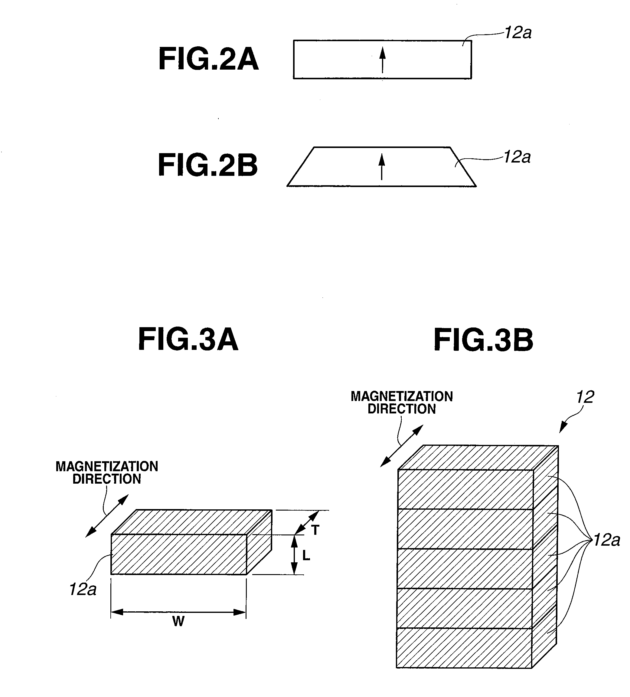
While division of a magnet body into smaller pieces leads to a more reduction of eddy current loss, it becomes necessary to take into account such problems as an increase of manufacturing cost and a lowering of output due to a reduction of magnet volume by increased interstices.
That is, the amount of heat generated by eddy currents is greater near the magnet surface, so that the magnet surface regio
Method used
View moreImage
Smart ImageViewing Examples

Examples
 PUM
 Abstract
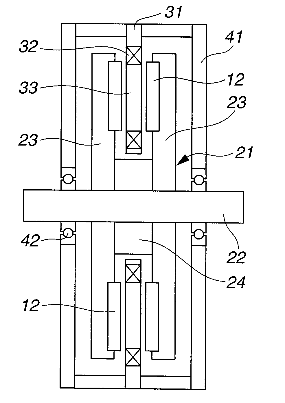
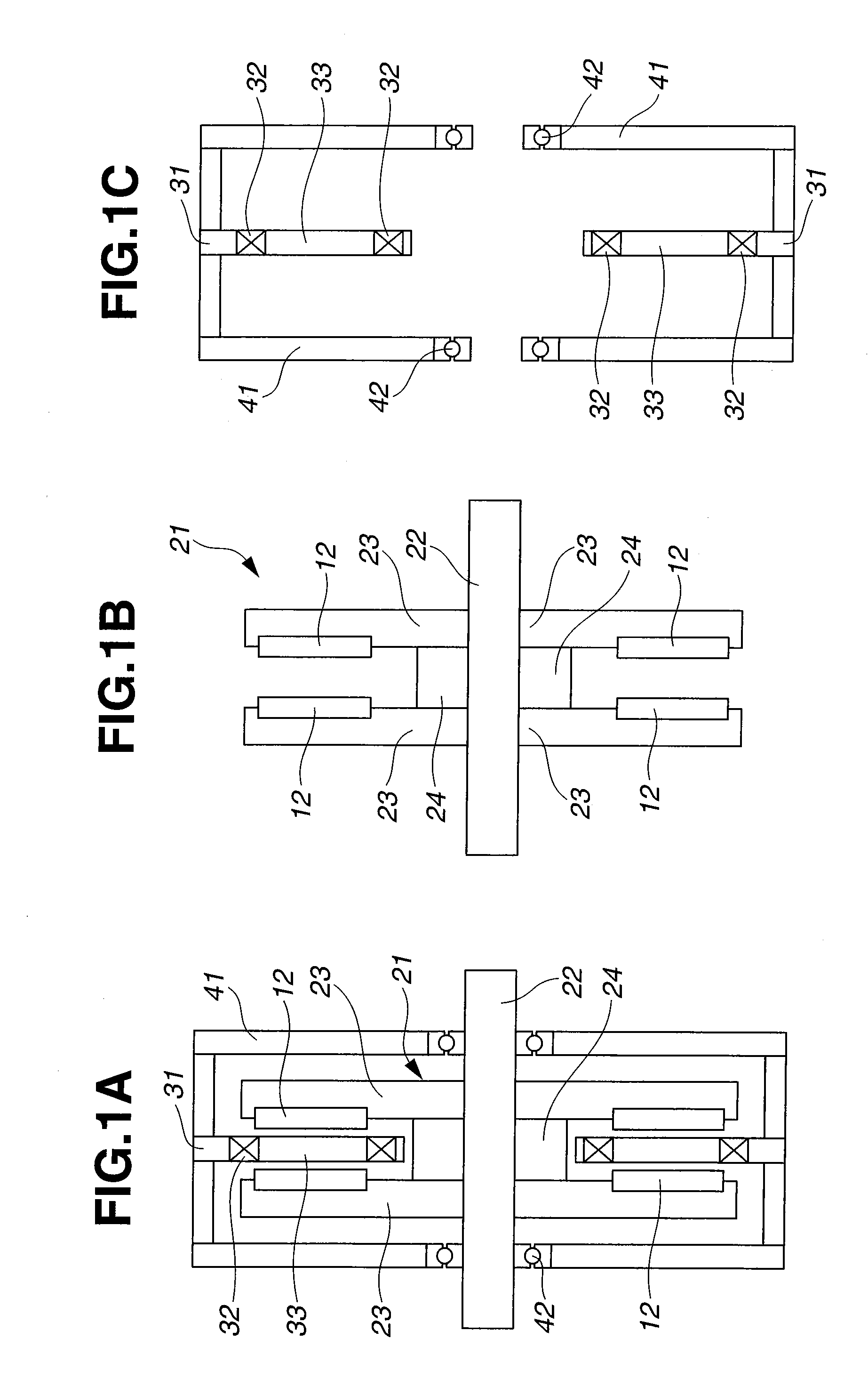
An axial gap-type permanent magnetic rotating machine comprises a rotor comprising a rotating shaft having an axis of rotation, a rotor yoke of disc shape radially extending from the shaft, and a plurality of permanent magnet segments circumferentially arranged on a surface of the rotor yoke such that each permanent magnet segment may have a magnetization direction parallel to the axis of rotation, and a stator having a plurality of circumferentially arranged coils and disposed to define an axial gap with the rotor. In the rotor, each permanent magnet segment is an assembly of two or more divided permanent magnet pieces, and the coercive force near the surface of the magnet piece is higher than that in the interior of the magnet piece.
Description
CROSS-REFERENCE TO RELATED APPLICATION[0001]This non-provisional application claims priority under 35 U.S.C. §119(a) on Patent Application No. 2009-229617 filed in Japan on Oct. 1, 2009, the entire contents of which are hereby incorporated by reference.TECHNICAL FIELD[0002]This invention relates to a synchronous permanent magnetic rotating machine, specifically an axial gap-type permanent magnetic rotating machine comprising a rotor comprising a rotating shaft having an axis of rotation, a rotor yoke of disc shape radially extending from the shaft, and a plurality of permanent magnet segments circumferentially arranged on a surface of the rotor yoke, and a stator having a plurality of circumferentially arranged coils and disposed to define an axial gap with the rotor. More particularly, it relates to the rotor in the permanent magnetic rotating machine, which is best suited as electric vehicle motors, power generators, and factory automation (FA) motors capable of high speed rotatio...
Claims
Login to View More Application Information
Patent Timeline
 IPC IPC(8): H02K21/24
CPCH02K1/2793H01F41/0293H02K1/2798H01F1/0536H01F7/11H02K21/24H02K16/02H02K2213/03
Inventor WATANABE, NAOKIDOI, YUHITOMINOWA, TAKEHISANAKAMURA, HAJIMEHIROTA, KOICHI
Owner SHIN ETSU CHEM IND CO LTD
Features
- Generate Ideas
- Intellectual Property
- Life Sciences
- Materials
- Tech Scout
- Unparalleled Data Quality
- Higher Quality Content
- 60% Fewer Hallucinations
Learn More Browse by: Latest US Patents, China's latest patents, Technical Efficacy Thesaurus, Application Domain, Technology Topic, Popular Technical Reports.
© 2025 PatSnap. All rights reserved.Legal|Privacy policy|Modern Slavery Act Transparency Statement|Sitemap|About US| Contact US: help@patsnap.com