Integrated Dual Swept Source for OCT Medical Imaging

a dual-swept source and swept source technology, applied in lasers, laser details, instruments, etc., can solve the problems of tuning speed and physical limits of current technology in terms of spectral width of scan bands, and achieve the effect of higher resolution and higher speed oct systems

Inactive Publication Date: 2011-04-07
EXCELITAS TECH
View PDF16 Cites 107 Cited by
  • Summary
  • Abstract
  • Description
  • Claims
  • Application Information

AI Technical Summary

Problems solved by technology

Physical limits exist with current technology in terms of the spectral width of the scan band, tuning speed, and realistic scan duty cycles.

Method used


Image

  • Integrated Dual Swept Source for OCT Medical Imaging
  • Integrated Dual Swept Source for OCT Medical Imaging
  • Integrated Dual Swept Source for OCT Medical Imaging

Examples


second embodiment

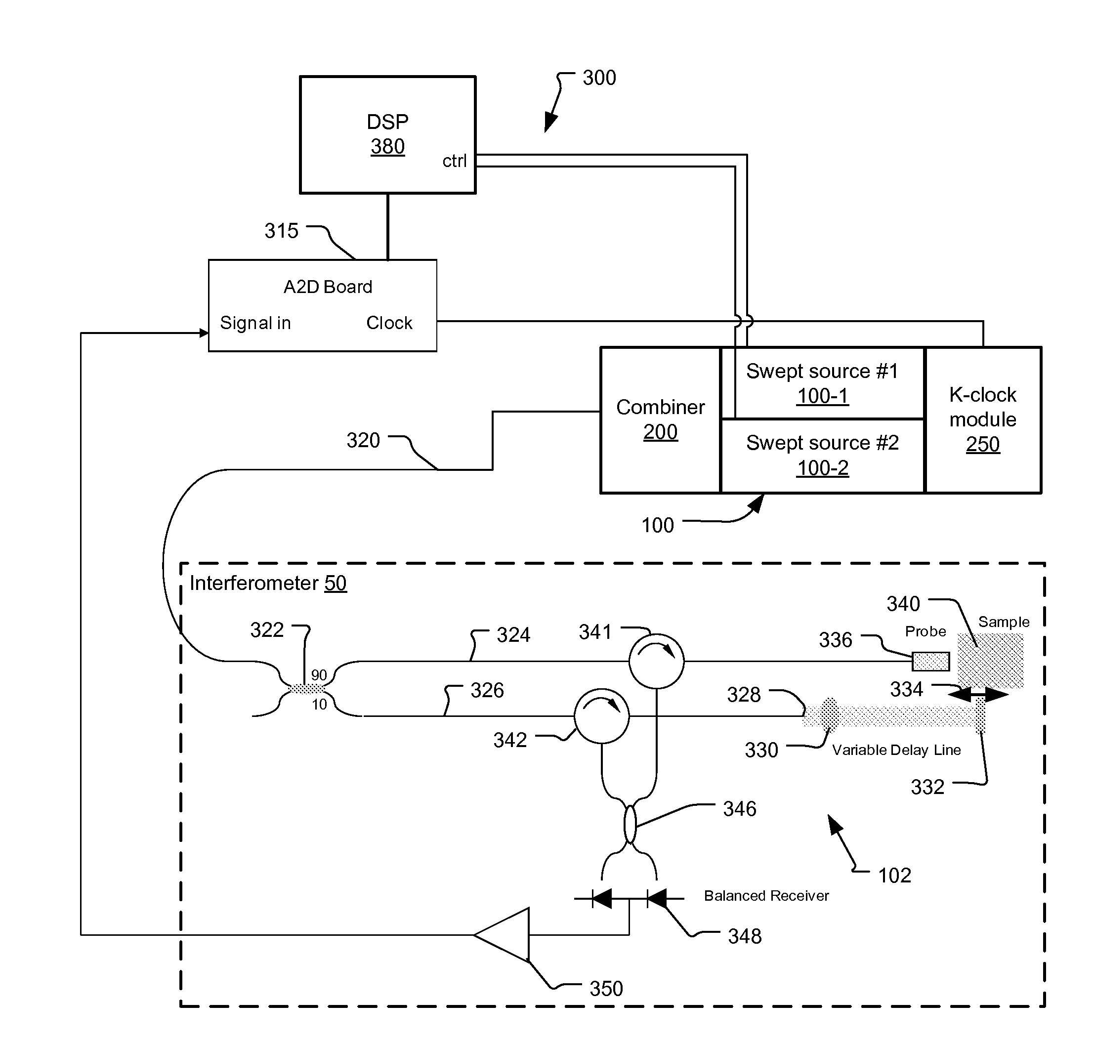
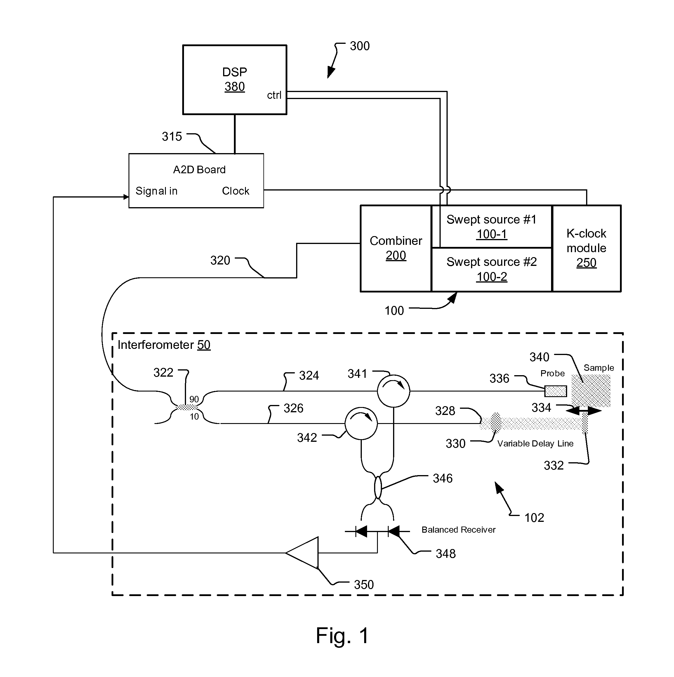
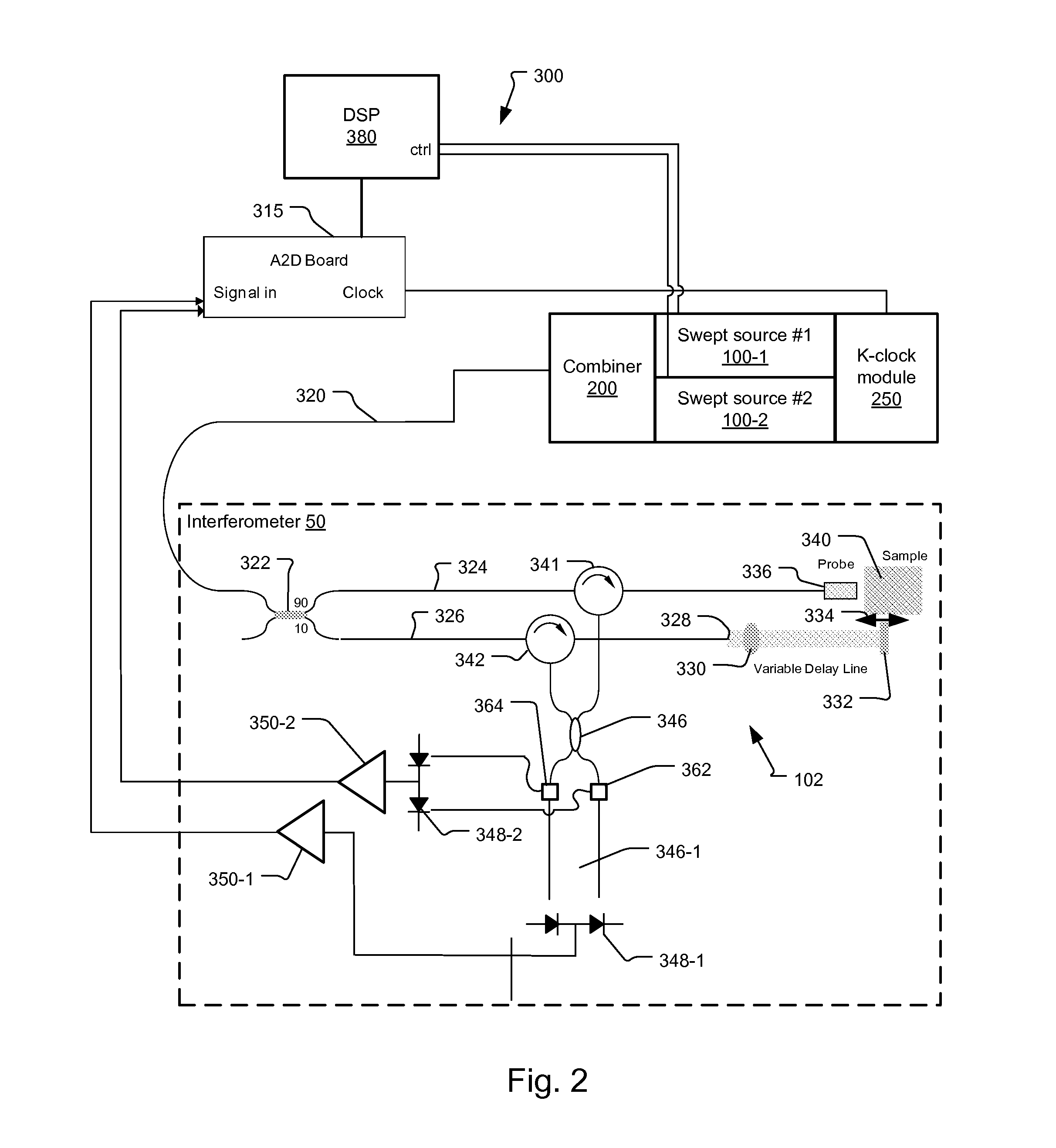
[0043]FIG. 2 shows an optical coherence analysis system 300 that has been constructed according to the present invention.

[0044]In this second embodiment, the dual swept source 100 and specifically the first swept source 100-1 and the second swept source 100-2 are not necessarily operated in a ping-pong fashion. At least, it is not a requirement that they are operated in this fashion. Instead, the first tunable optical signal from the first swept source 100-1 and the second tunable optical signal from the second swept source 100-2 are separated either in wavelength and / or polarization. As a result, the combined optical signal on optical fiber 320 in one implementation of this embodiment, is at any instant a combination of the first tunable optical signal and the second tunable optical signal.

[0045]To deal with this situation, the detector system has the capacity to separate the interference signal into portions derived from first tunable optical signal and the second tunable optical ...

first embodiment

[0048]FIG. 3 shows the dual swept optical source 100 that has been constructed according to the principles of the present invention.

[0049]The first and the second swept sources 100-1 and 100-2 are each filtered amplified spontaneous emission sources. In the current embodiments these ASE swept sources 100-1 and 100-2 are any one of ASE swept sources described in U.S. patent application Ser. No. 12 / 553,295, entitled Filtered ASE Swept Source for OCT Medical Imaging, filed on Sep. 3, 2009 by Flanders, et al. Additionally, other amplified ASE swept sources could be used in still further examples. Nevertheless, the following example is provided based on one of the swept source configurations of this incorporated document.

[0050]In more detail, the swept sources 100-1, 100-2 each comprise a broadband source 112-1, 112-2 that generates a broadband optical signal. In general, the broadband signal is characterized by a continuous spectrum that extends in wavelength over at least 40 nanometers...


PUM


Abstract

An optical coherence analysis system comprising: a first swept source that generates a first optical signal that is tuned over a first spectral scan band, a second swept source that generates a second optical signal that is tuned over a second spectral scan band, a combiner for combining the first optical signal and the second optical signal for form a combined optical signal, an interferometer for dividing the combined optical signal between a reference arm leading to a reference reflector and a sample arm leading to a sample, and a detector system for detecting an interference signal generated from the combined optical signal from the reference arm and from the sample arm.

Description

BACKGROUND OF THE INVENTION[0001]Optical coherence analysis relies on the use of the interference phenomena between a reference wave and an experimental wave or between two parts of an experimental wave to measure distances and thicknesses, and calculate indices of refraction of a sample. Optical Coherence Tomography (OCT) is one example technology that is used to perform usually high-resolution cross sectional imaging. It is often applied to imaging biological tissue structures, for example, on microscopic scales in real time. Optical waves are reflected from an object or sample and a computer produces images of cross sections of the object by using information on how the waves are changed upon reflection.[0002]The original OCT imaging technique was time-domain OCT (TD-OCT), which used a movable reference mirror in a Michelson interferometer arrangement. In order to increase performance, variants of this technique have been developed using two wavelengths in so-called dual band OCT...

Claims


Application Information

Patent Timeline
Patent Type & Authority Applications(United States)
IPC IPC(8): G01B9/02
CPCH01S3/1062H01S3/2383H01S5/141G01B9/02069G01B9/02007G01B9/02091G01B9/02004
Inventor JOHNSON, BARTLEY C.ATIA, WALID A.KUZNETSOV, MARK E.FLANDERS, DALE C.
Owner EXCELITAS TECH
Why Eureka
Try Eureka