
Foldable Light Source Module and Backlight Module with the Light Source Module

a backlight module and light source technology, applied in the direction of lighting and heating apparatus, lighting support devices, instruments, etc., can solve the problem of difficulty in meeting the brightness requirement by increasing the amount of led, and achieve the effect of increasing the density of light sources and fixing the length of the effective display region of the flat panel display

Active Publication Date: 2011-04-07
AU OPTRONICS CORP
View PDF6 Cites 14 Cited by
  • Summary
  • Abstract
  • Description
  • Claims
  • Application Information

AI Technical Summary

Benefits of technology

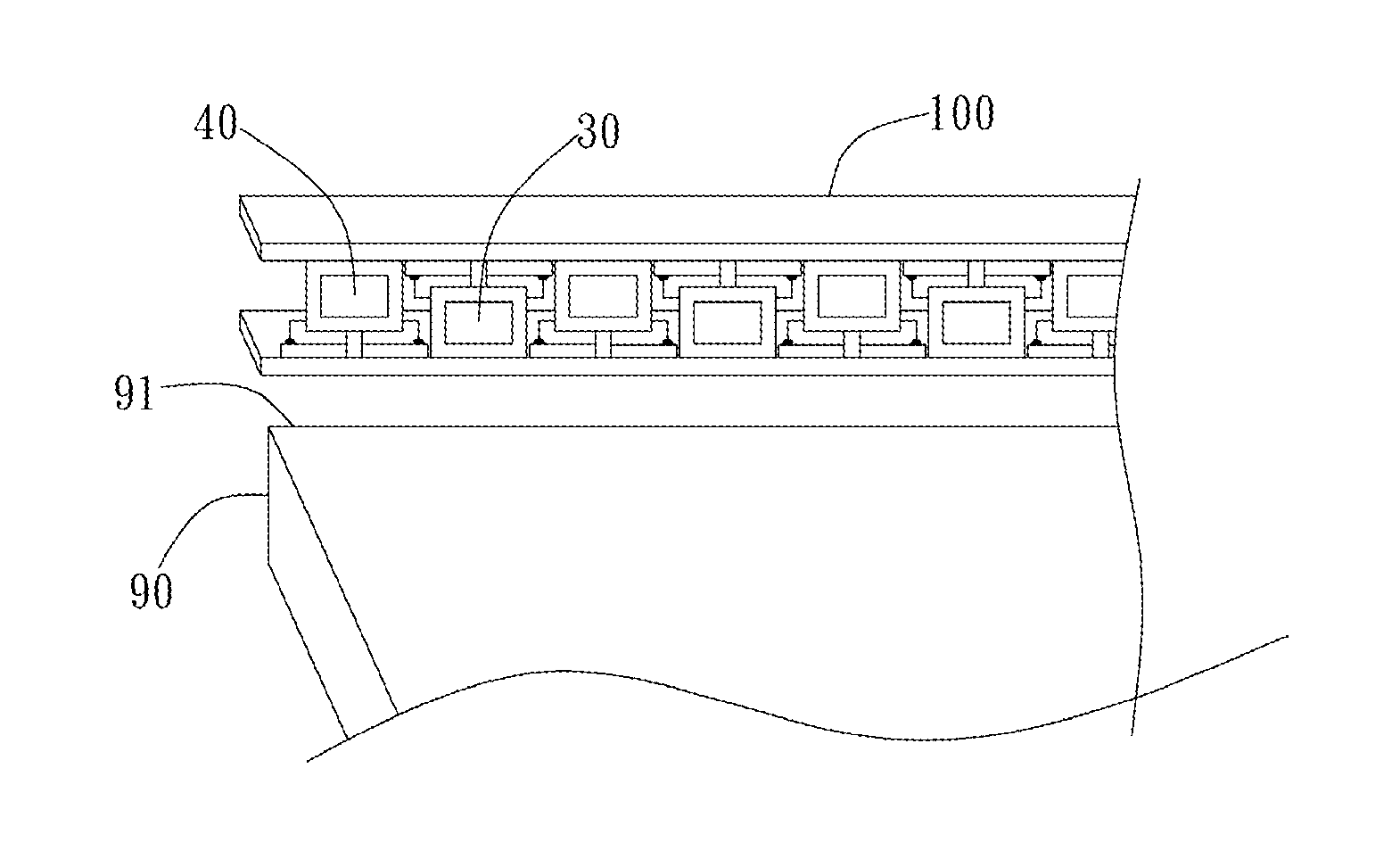
[0008]It is an objective of the present invention to provide a foldable light source module and a backlight module with the light source module, so as to increase the density of the light emitting elements in the light source module. As such, the brightness of flat panel display can be enhanced to improve the above-mentioned problems of prior art. Moreover, since the distance between light emitting elements are shortened, the required light mixing distance between the light source module and the optical film is correspondingly shortened.
[0010]The light source module of the present invention increases the density of light sources by interlacing two sets of light sources of opposite extending directions, so that more light sources can be disposed to meet severe brightness requirement while the length of effective display region of a flat panel display is fixed.

Problems solved by technology

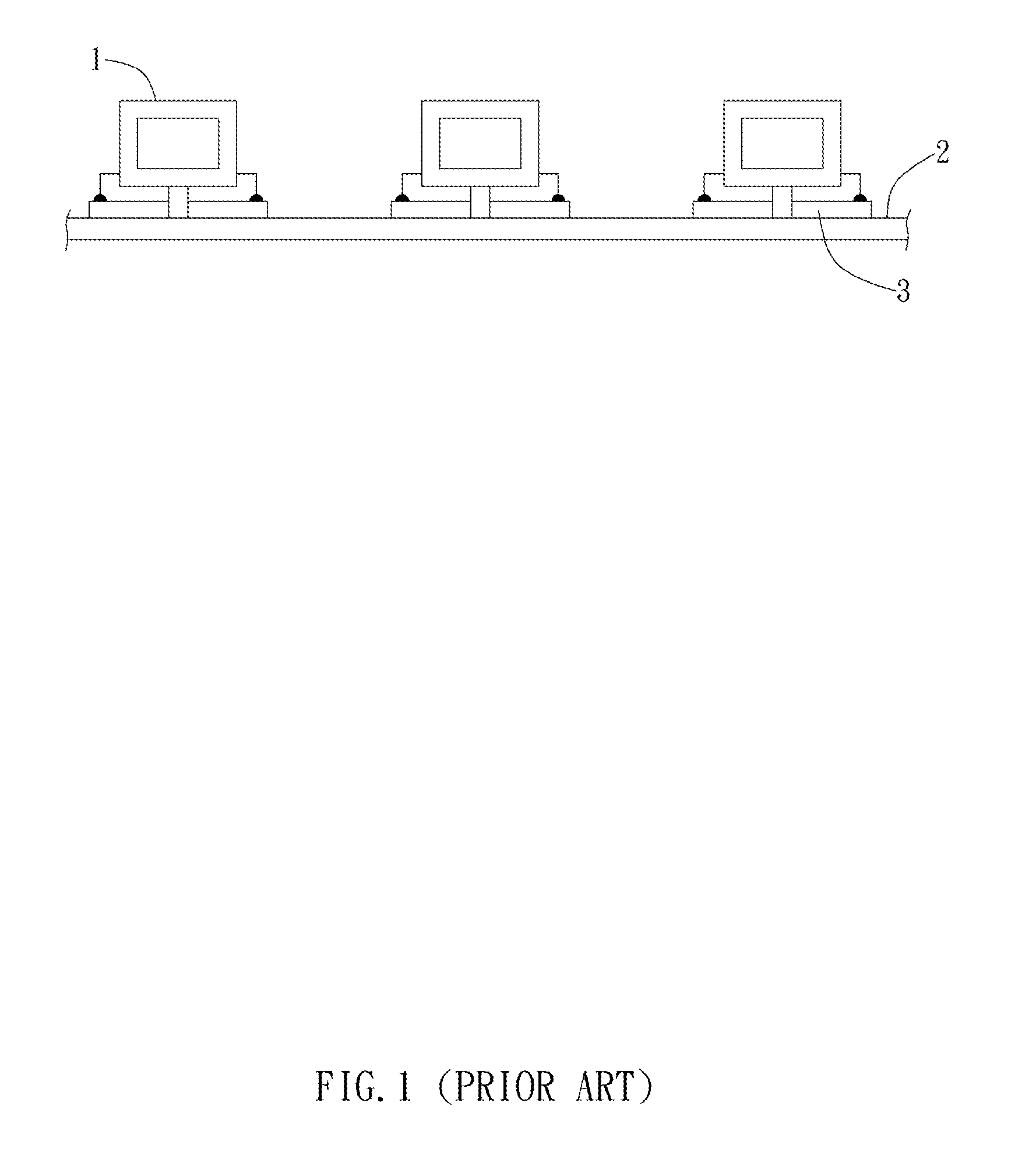
Hence, for the higher brightness requirement of LCDs which employ conventional LED disposing manner, especially when the volume is restricted, it is difficult to meet the brightness requirement by increasing the amount of LED.

Method used


Image

  • Foldable Light Source Module and Backlight Module with the Light Source Module
  • Foldable Light Source Module and Backlight Module with the Light Source Module
  • Foldable Light Source Module and Backlight Module with the Light Source Module

Examples


first embodiment

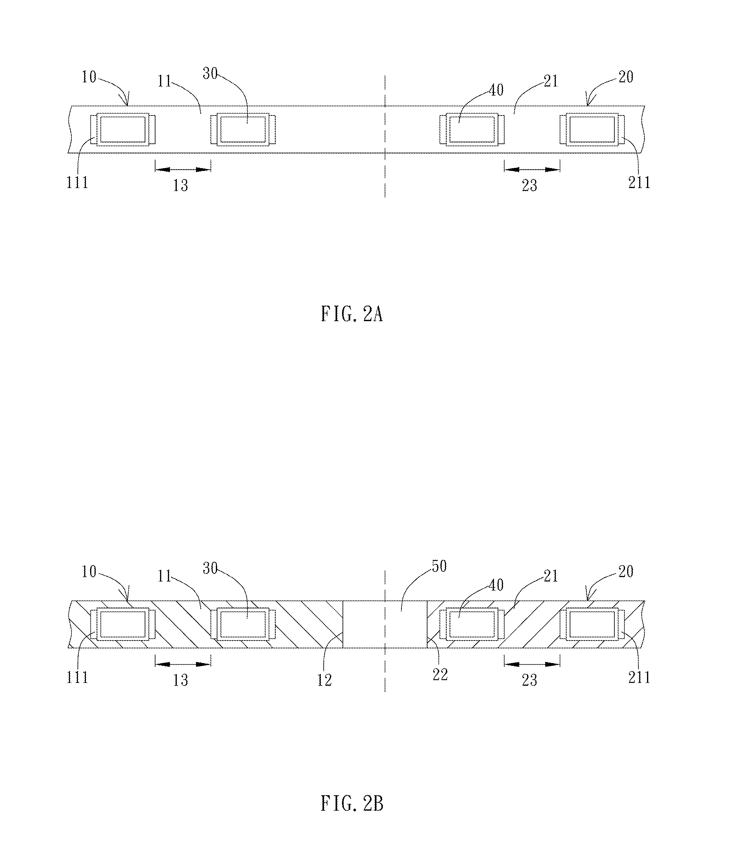
[0024]FIG. 2A is a schematic view of a light source module of the present invention before folded. As shown in FIG. 2A, the light source module includes a first substrate 10, a second substrate 20, first light sources 30, and second light sources 40. In a preferred embodiment, the first light sources 30 and the second light sources 40 are side-view LEDs, i.e. LEDs emit light from their sides. In this embodiment, the first substrate 10 and the second substrate 20 are respectively two ends of a folded long-strip flexible circuit board.

second embodiment

[0025]FIG. 2B is a schematic view of a light source module of the present invention before folded. As shown in FIG. 2B, the first substrate 10 and the second substrate 20 are two different circuit boards, wherein the substrates can be both flexible circuit boards or at least one of them is a rigid circuit board. The first substrate 10 and the second substrate 20 are disposed and extended in opposite directions to form a straight line. The first substrate 10 is a long-strip shape and has a first surface 11 and a first connecting portion 12, wherein the first connecting portion 12 is at one end of the first substrate 10 which corresponds to the second substrate 20. The first light sources 30 are disposed on the first surface 11 in a line along a direction away from the first connecting portion 12, i.e., disposed from one end near the first connecting portion 12 toward the other end, so that a first gap 13 is kept between the neighboring first light sources 30. The second substrate 20 ...

fourth embodiment

[0030]FIG. 4 is a schematic view of a light source module of the present invention. As shown in FIG. 4, the adjacent first light sources 30 and second light sources 40 are in contact with each other. A gap 80 is respectively kept between the first light source 30 and the second surface 21 or between the second light source 40 and the first surface 11.


PUM


Abstract

A foldable light source module and a backlight module with the light source module are provided. The light source module includes a first substrate, first light sources, a second substrate, and second light sources. The first substrate has a first surface and a first connecting portion. The first light sources are arranged in a line and disposed on the first surface. A first gap is kept between the neighboring first light sources. The second substrate which has a second surface and a second connecting portion is disposed parallel to the first substrate, wherein the second surface faces the first surface, and the second connecting portion connects to the first connecting portion. The second light sources are arranged in a line and disposed on the second surface. A second gap is kept between the neighboring second light sources. At least a portion of the second light source extends into the corresponding first gap and, conversely, at least a portion of the first light source extends into the corresponding second gap.

Description

[0001]This application claims priority based on a Taiwanese Patent Application No. 098133453, filed on Oct. 1, 2009, the disclosure of which is incorporated herein by reference in its entirety.BACKGROUND OF THE INVENTION[0002]1. Field of the Invention[0003]The present invention relates to a light source module and a backlight module with the light source module; particularly, the present invention relates to the structure of a light source module and a backlight module with the light source module.[0004]2. Description of the Related Art[0005]Since the liquid crystal of liquid crystal display (LCD) can not emit light itself, a backlight module is often employed as the light source. At present, the most common light sources are made of light emitting diode (LED) and cold cathode fluorescent lamp (CCFL). The selection of light source depends on various factors such as the size of display panel, the brightness requirements, the demand of power saving, etc.[0006]FIG. 1 is a schematic vie...

Claims


Application Information

Patent Timeline
Patent Type & Authority Applications(United States)
IPC IPC(8): F21V7/22F21S4/00
CPCG02B6/0068G02B6/0073G02B6/009G02B6/0083
Inventor WANG, CHING-HUI
Owner AU OPTRONICS CORP
Learn More