Climate Control System And Method For Optimizing Energy Consumption of A Vehicle

a technology of climate control system and vehicle, applied in adaptive control, heating types, instruments, etc., can solve the problems of significant fuel economy penalties, loss of cooling capacity of a/c system, and large energy consumption of air conditioning compressor operation

Active Publication Date: 2011-04-07
FORD GLOBAL TECH LLC
View PDF12 Cites 47 Cited by
  • Summary
  • Abstract
  • Description
  • Claims
  • Application Information

AI Technical Summary

Problems solved by technology

Conventional automatic temperature control allows users to set extreme temperature set points often resulting in significant fuel economy penalties.
However, operation of the air conditioning compressor uses a relatively large

Method used


Image

  • Climate Control System And Method For Optimizing Energy Consumption of A Vehicle
  • Climate Control System And Method For Optimizing Energy Consumption of A Vehicle
  • Climate Control System And Method For Optimizing Energy Consumption of A Vehicle

Examples


Embodiment Construction

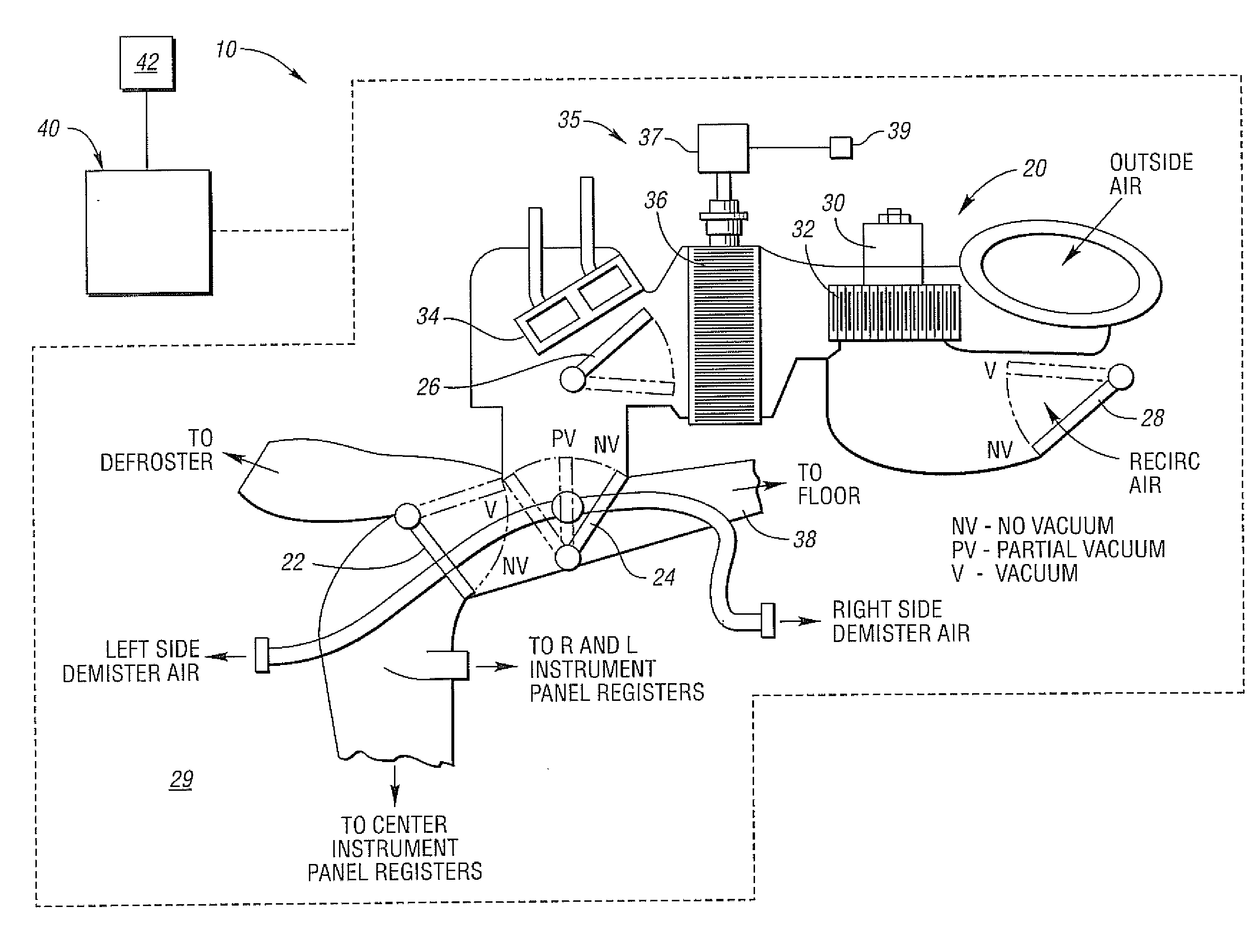
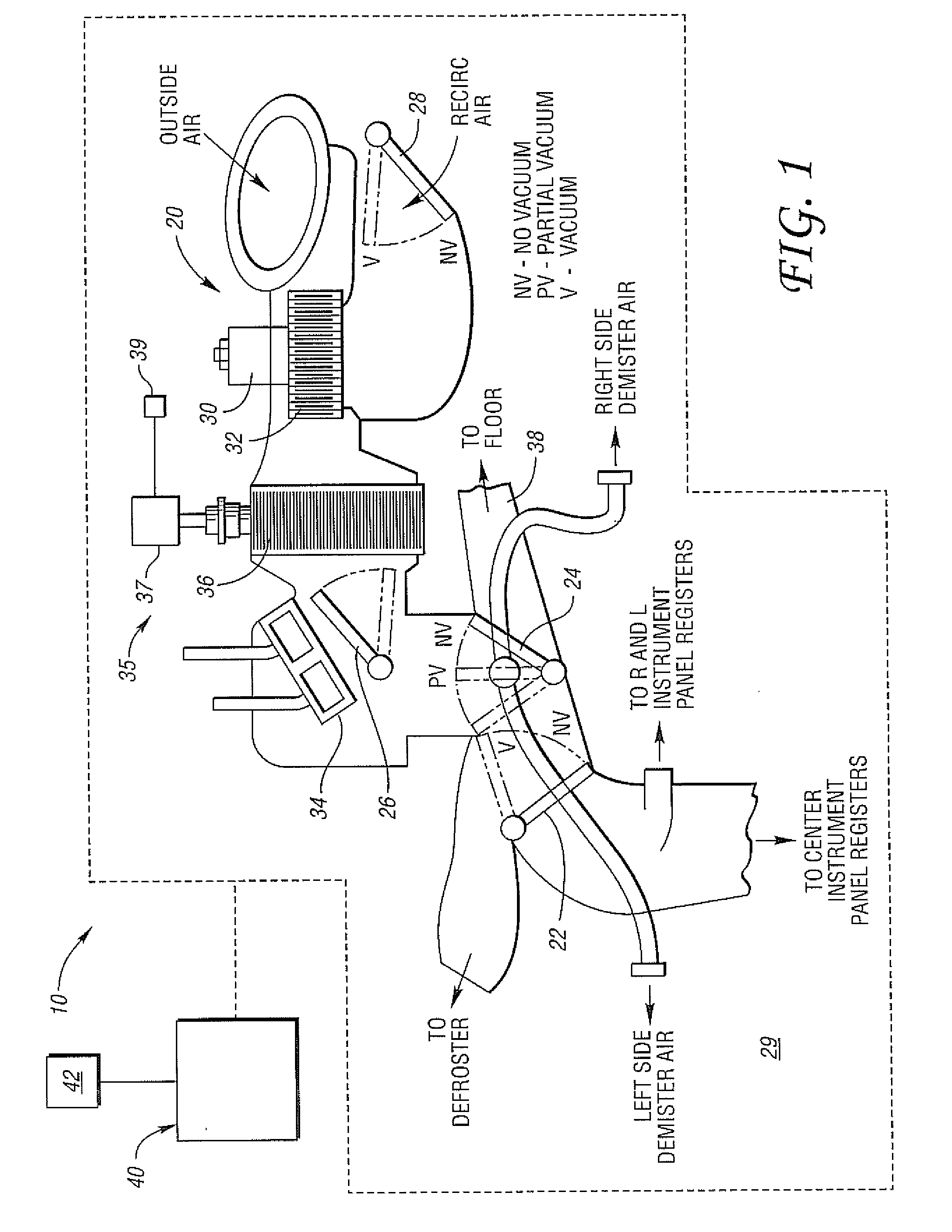
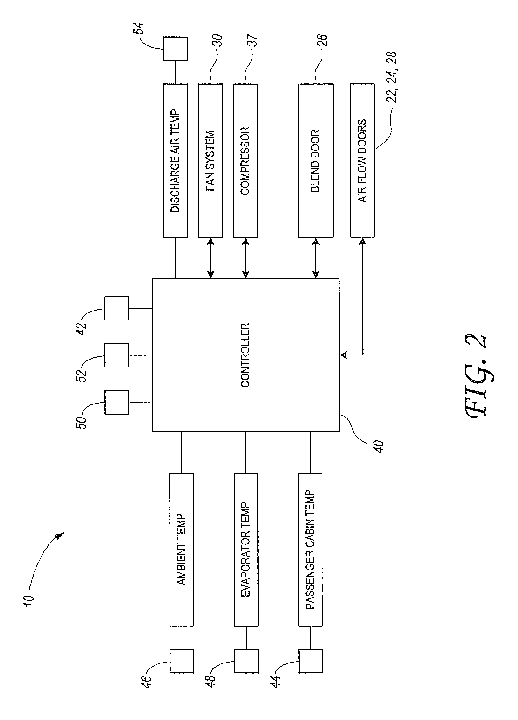
[0019]In general, control of cabin temperature, as well as temperature and defogging of a windshield, within an automobile is accomplished using various actuators to adjust the temperature and flow of air supplied to the cabin of the vehicle. FIG. 1 schematically shows an exemplary climate control system 10 for environmental management of a vehicle in accordance with an embodiment of the present application. The vehicle may include a heating, ventilating and air conditioning (HVAC) system, generally indicated at 20. The HVAC system 20 can include the arrangement of airflow doors, including panel-defrost, floor-panel, and outside recirculated air actuators or doors 22, 24, and 28, respectively.

[0020]The doors may be part of an air distribution system for directing the flow of conditioned air to various locations within a passenger cabin 29 of the vehicle, such as to the windshield, floor, or instrument panel as is commonly known. The doors 22, 24 and 28 may be driven by vacuum motors...


PUM


Abstract

A climate control system includes a control head having a warmer/cooler temperature control for providing relative thermal comfort. A thermal comfort rating (TCR) corresponding to a range of passenger cabin temperatures is determined based upon a comfort level selection by an occupant using the control head. A control strategy employs look-up tables corresponding to the TCR to determine the speed of an electric compressor and the position of a temperature control blend door. The strategy provides for a relatively fast ramp down to a minimum compressor speed to improve fuel economy while maintaining a relative level of thermal comfort.

Description

BACKGROUND[0001]1. Technical Field[0002]The present invention relates to a climate control system and method, and more particularly a climate control strategy utilizing vehicle occupant comfort level settings to optimize fuel economy.[0003]2. Background Art[0004]Automatic climate control is increasingly prevalent in vehicles today. In some vehicles, a driver merely chooses a temperature setting through a climate control head unit, and a control system operates a climate control system to achieve the desired temperature. The climate control system may control the functions of a fan—e.g., on / off and fan speed—and an air conditioning (A / C) system. Such a climate control system may also control the position and movement of various air dampers, or air flow doors, to control movement of air through an evaporator core or a heater core, the recirculation of air through the vehicle, the intake of fresh air, or some combination thereof.[0005]Conventional automatic temperature control allows u...

Claims


Application Information

Patent Timeline
IPC IPC(8): G05B15/00G05D22/02
CPCF24F11/008B60H1/00985F24F11/83
Inventor DAGE, GERHARD A.WIJAYA, HALIMGREINER, CHRISTOPHER MARKBUESCHER, WAYNE FRANK
Owner FORD GLOBAL TECH LLC
Why Eureka
Try Eureka