
Location enhancement system and method based on topology constraints

a topology constraint and enhancement system technology, applied in surveying and navigation, navigation instruments, instruments, etc., can solve the problems of inability to accurately locate, track and monitor personnel within, so as to improve accuracy, the disclosed location system may be further improved

Active Publication Date: 2011-04-07
HONEYWELL INT INC
View PDF12 Cites 33 Cited by
  • Summary
  • Abstract
  • Description
  • Claims
  • Application Information

AI Technical Summary

Benefits of technology

[0007]It is, therefore, one aspect of the disclosed embodiments to provide for an improved location tracking system and method for tracking people and assets in variable environments.
[0008]It is another aspect of the disclosed embodiments to provide for an accurate position location and tracking system and method for use with a wide range of facilities.
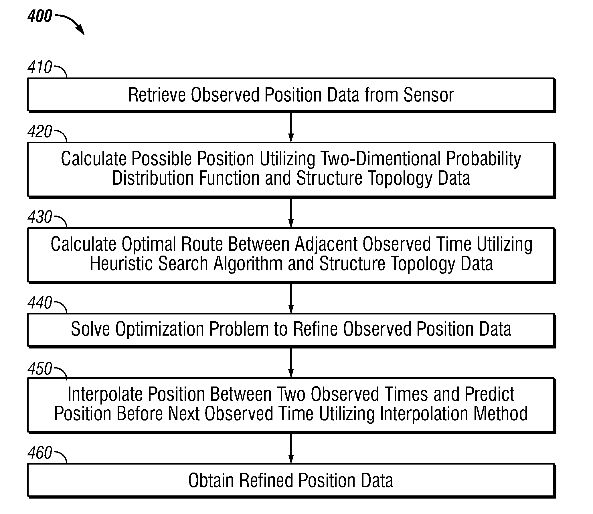
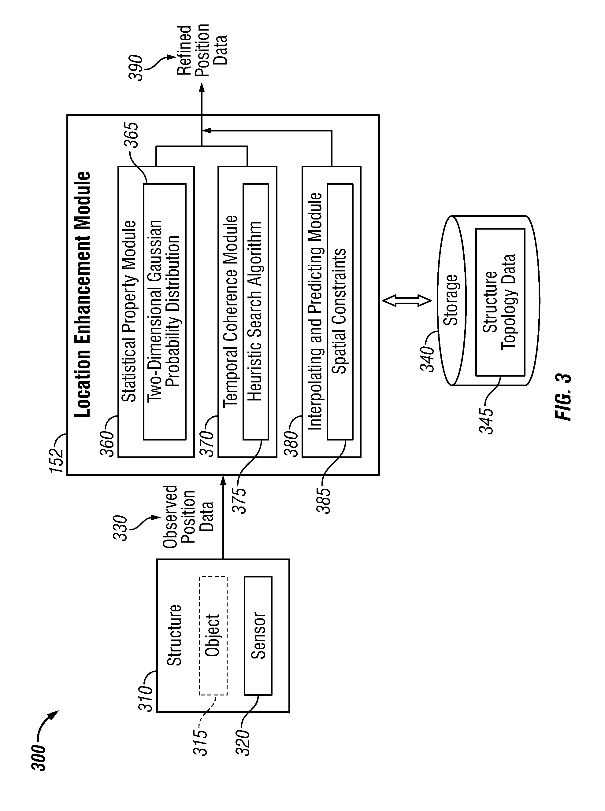
[0010]The aforementioned aspects and other objectives and advantages can now be achieved as described herein. A method and system for enhancing location sensing based on topology constraints (e.g., statistical property data, temporal coherence values, spatial constraints, etc) is disclosed. A potential position value and a corresponding probability value with respect to an observed position data of an object (e.g., personnel, equipment, and other tangibles) within a structure can be calculated utilizing a normal probability distribution function (e.g., two-dimensional Gaussian probability distribution function). Thereafter, an optimal route between adjacent observed time periods can be calculated utilizing a heuristic search algorithm (e.g., A* heuristic route search approach). The potential position value and the optimal route can be calculated by accessing pre-installed topology data associated with the structure. An optimization problem can then be solved to refine the observed position data. The position between a pair of observed time periods can be interpolated and the position of the object before a next observed time can be predicted utilizing an interpolation method (e.g., linear interpolation, polynomial interpolation, a Bezier or NURBUS interpolation, etc) based on the spatial constraints. The approach described herein can therefore enhance location sensing in order to effectively locate and track an object.
[0012]The disclosed heuristic search algorithm can split an image obtained from the structure topology data into grids. In the context of an office building or other similar complex, walls and / or cubicles may be marked as a red grid with an unlimited weight value and any open spaces, wherein a person may walk, can be marked with a green grid with a particular weight value. The heuristic search algorithm can search the optimal route between any two grids and then calculate a route length. Probability values and the length of the optimal routes can be utilized to refine the observed position data. The position at any time between the pair of observed time periods can then be obtained by implementing a curve fitting process. The position before the next observed time can also be predicted to improve accuracy. The predicted position can then be located on the fitting curve. The disclosed location system may be further improved by applying a second-order Markov property, adding a moving velocity and a moving direction, and solving the optimization problem.

Problems solved by technology

A common problem encountered by first responders is the difficulty in capturing and transmitting accurate and up to date information to a command center and then providing such information to the first responders who responds on site to the incident.
Current first responder systems are unable to accurately locate, track and monitor personnel within a structure during an incident, visualize the location and track the responders on a geospatial map and / or structure, and provide such information in a standard and efficient manner to the interested parties during the incident.
The error between an observed location and a real location, however, is still unavoidable due to various factors such as, for example, signal intervention, various infrastructures, and so on.

Method used


Image

  • Location enhancement system and method based on topology constraints
  • Location enhancement system and method based on topology constraints
  • Location enhancement system and method based on topology constraints

Examples


Embodiment Construction

[0020]The particular values and configurations discussed in these non-limiting examples can be varied and are cited merely to illustrate at least one embodiment and are not intended to limit the scope thereof.

[0021]The disclosed embodiments can be utilized to automatically locate, monitor and track objects such as, for example, personnel, equipment, and other tangibles within a structure during an incident. The approach described herein can provide enhanced location information of such an object utilizing topology constraints associated with the structure.

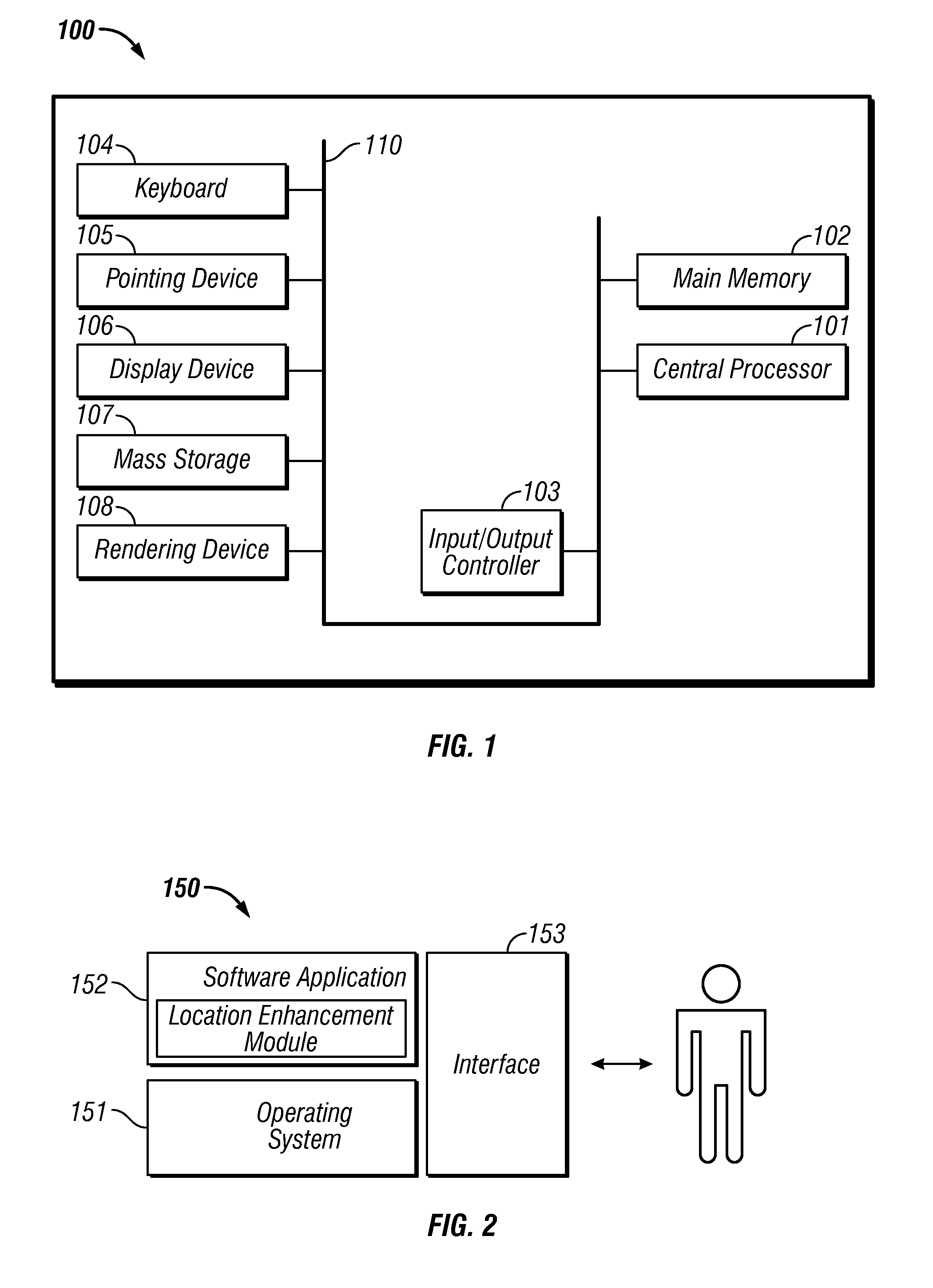
[0022]The following discussion is intended to provide a brief, general description of suitable computing environments in which the system and method may be implemented. Although not required, the disclosed embodiments will be described in the general context of computer-executable instructions, such as program modules, being executed by a single computer.

[0023]Generally, program modules include routines, programs, objects, componen...


PUM


Abstract

A method for enhanced location sensing based on topology constraints. A potential position value and a corresponding probability value with respect to an observed position data of an object within a structure can be calculated utilizing a normal probability distribution function. Thereafter, an optimal route between adjacent observed time periods may be calculated utilizing a heuristic search algorithm. The potential position value and the optimal route can be calculated by accessing a pre-installed topology data associated with the structure. An optimization problem can then be solved to refine the observed position data. The position between a pair of observed time periods can be interpolated and the position of the object before a next observed time can be predicted by interpolation based on the spatial constraints.

Description

TECHNICAL FIELD[0001]Embodiments are generally related to location tracking systems and methods. Embodiments also relate in general to the field of computers and similar technologies and, in particular, to software utilized in this field. Embodiments are additionally related to the enhancement of location tracking systems based on topology constraints.BACKGROUND OF THE INVENTION[0002]In some situations, it may be desirable to determine the location and / or movement of a person or another object within a building or a relatively well defined space such as a home, a hospital, a prison, etc. Large facilities may be subject to incidents or other events that need to be handled rapidly and efficiently by first responders such as, for example, firefighters, police officers, search and rescue teams, and so forth. A common problem encountered by first responders is the difficulty in capturing and transmitting accurate and up to date information to a command center and then providing such info...

Claims


Application Information

Patent Timeline
Patent Type & Authority Applications(United States)
IPC IPC(8): G01C21/30
CPCG01C21/20
Inventor HUSETH, STEVECHEN, HENRYPLOCHER, TOM
Owner HONEYWELL INT INC
Learn More