System and method for view-dependent anatomic surface visualization

a view-dependent, anatomic surface technology, applied in the field of surface models, can solve the problems of difficult viewing through closed opaque surfaces, user may still need, and the x-ray fluoroscopy does not depict the la and pvs well, and achieves the effects of facilitating a change of opacity, simple segmentation threshold, and enhancing the user's understanding of a patient's anatomy

Inactive Publication Date: 2011-04-07
SIEMENS AG
View PDF8 Cites 21 Cited by
  • Summary
  • Abstract
  • Description
  • Claims
  • Application Information

AI Technical Summary

Benefits of technology

[0008]Exemplary embodiments of the invention as described herein generally include methods and systems for simultaneous visualization of the outside and the inside of a surface model at a selected view orientation. A method according to an embodiment of the invention allows simultaneous visualization of the outside and the inside of a surface model at a selected view orientation, by placing a camera outside of the surface, and by automatically displaying the surface in a way that attempts to predict how medical staff personnel would like to see it. This personalized display of a surface according to an embodiment of the invention is referred to herein as a carving, or a carved rendering. A method according to an embodiment of the invention is view-aligned, being based on the angle between the normal vector at the surface and the camera view direction, and can adapt to both view direction and the local surface shape. A carving update can be computed in real-time that adjusts to a new view direction. A method according to an embodiment of the invention allows the user to obtain a 3D perspective of surface from the outside, and by using a simple segmentation threshold, can reveal as much of the internal surface and graphics as desired. This way, users can tune the technique to match their specific needs. Unlike clipping tools, carving is not bound to some predefined shape of the clipping tool (typically a plane). Instead, carving depends on the local curvature of the surface and its orientation with respect to the viewing direction. A method according to an embodiment of the invention does not necessarily use semi-transparency, so graphic blending is not required. A method according to an embodiment of the invention can facilitate a change of opacity or remove parts of the surface to reveal anatomical details on the inside in the back of the surface (“back surface”), which can enhance the user's understanding of a patient's anatomy. A method according to an embodiment of the invention can support carving of the front face of an object, carving of the back face of an object, or any combination thereof.

Problems solved by technology

However, X-ray fluoroscopy does not depict the LA and PVs well, because the LA and PVs are made up of soft-tissue.
However, viewing through a closed opaque surface is a challenge.
Even view-aligned clipping planes pose a challenge, by restricting the orientation of the clipping plane.
However, a user may still need to select the actual position of the clipping plane.
However, since the graphics are blended, the internal graphics and the external graphics are not clearly distinguishable.

Method used


Image

  • System and method for view-dependent anatomic surface visualization
  • System and method for view-dependent anatomic surface visualization
  • System and method for view-dependent anatomic surface visualization

Examples


Embodiment Construction

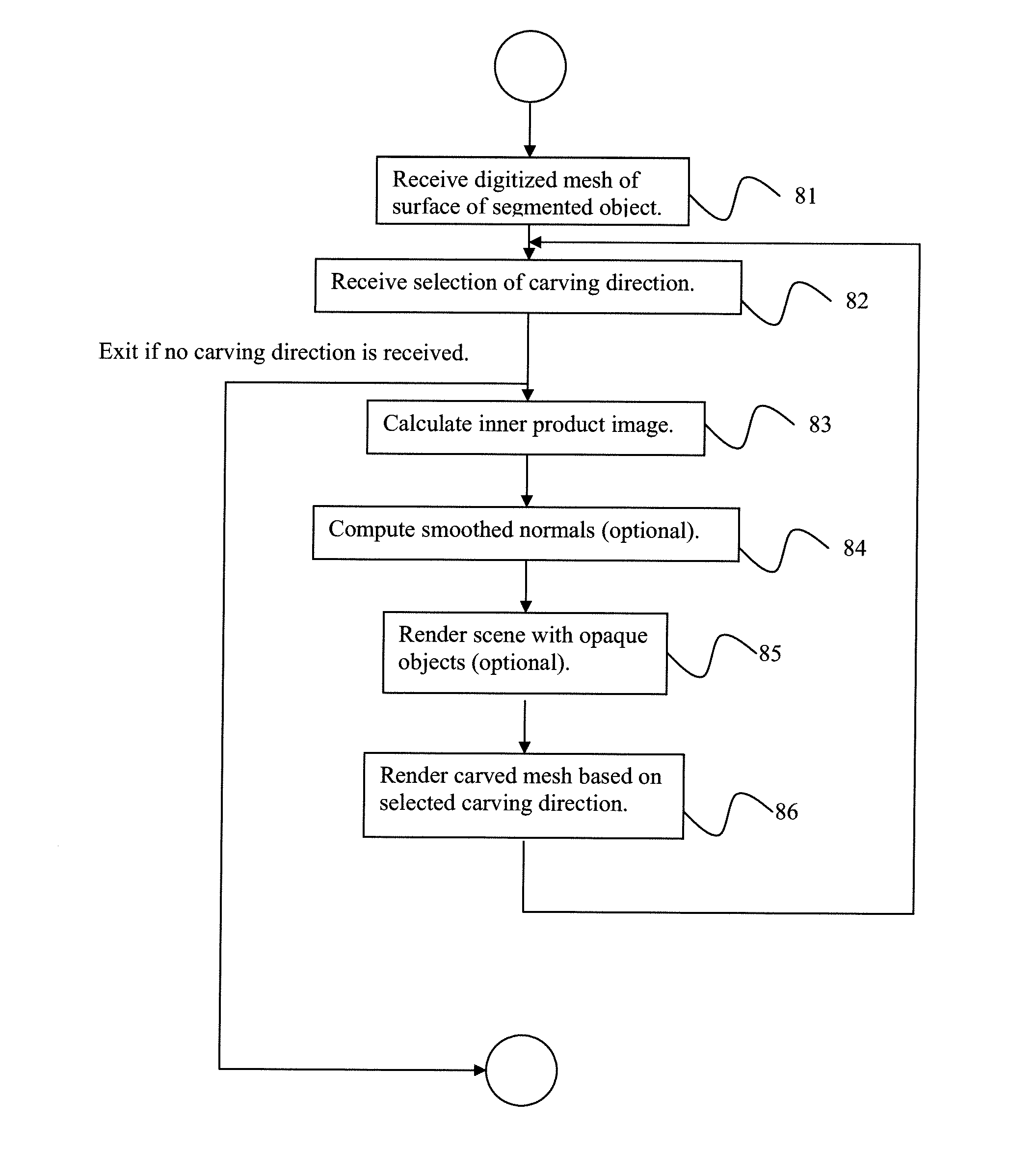
[0034]Exemplary embodiments of the invention as described herein generally include systems and methods for simultaneously visualizing the outside and the inside of a surface model at a selected view orientation. Accordingly, while the invention is susceptible to various modifications and alternative forms, specific embodiments thereof are shown by way of example in the drawings and will herein be described in detail. It should be understood, however, that there is no intent to limit the invention to the particular forms disclosed, but on the contrary, the invention is to cover all modifications, equivalents, and alternatives falling within the spirit and scope of the invention.

[0035]As used herein, the term “image” refers to multi-dimensional data composed of discrete image elements (e.g., pixels for 2-D images and voxels for 3-D images). The image may be, for example, a medical image of a subject collected by computer tomography, magnetic resonance imaging, ultrasound, or any other...


PUM


Abstract

A method for simultaneous visualization of the outside and the inside of a surface model at a selected view orientation includes receiving a digitized representation of a surface of a segmented object, where the surface representation comprises a plurality of points, receiving a selection of a viewing direction for rendering the object, calculating an inner product image be calculating an inner product {right arrow over (n)}p·{right arrow over (d)} at each point on the surface mesh, where {right arrow over (n)}p is a normalized vector representing the normal direction of the surface mesh at a point p towards the exterior of the object and {right arrow over (d)} is a normalized vector representing the view direction, and rendering the object using an opacity that is a function of the denoised inner product image to yield a rendered object, where an interior of the object is rendered.

Description

CROSS REFERENCE TO RELATED UNITED STATES APPLICATIONS[0001]This application claims priority from “View-depended Anatomic Surface Visualization”, U.S. Provisional Application No. 61 / 249,014 of Ibarz, et al., filed Oct. 6, 2009, the contents of which are herein incorporated by reference in their entirety.TECHNICAL FIELD[0002]This disclosure is directed to methods of visualizing surface models of an anatomical structure.DISCUSSION OF THE RELATED ART[0003]Many clinical applications use surface rendering of anatomic structures to allow clinical staff to view and interact with the data for interventional and diagnostic purposes. Surfaces involved are usually generated using imaging modalities such as computed tomography (CT), magnetic resonance imaging (MRI), or C-arm CT. In some cases, however, it is useful for a physician to not only see the outside but also view the inside of a surface model. This is to either study the internal shape or view additional graphics that are placed on the ...

Claims


Application Information

Patent Timeline
Patent Type & Authority Applications(United States)
IPC IPC(8): G06F17/50
CPCG06T15/503G06T2210/62G06T17/00
Inventor IBARZ, JULIANYATZIV, LIRONSTROBEL, NORBERT
Owner SIEMENS AG
Why Eureka
Try Eureka