
Multi-spindle machining machine with tool changing mechanism

a multi-spindle machining machine and tool changing technology, applied in the direction of feeding apparatus, process and machine control, wood working apparatus, etc., can solve the problems of tool changing time, increasing size, production cost, etc., to enhance tool changing efficiency and reduce size and production cost.

Inactive Publication Date: 2011-04-14
SHENQ FANG YUAN TECH
View PDF10 Cites 25 Cited by
  • Summary
  • Abstract
  • Description
  • Claims
  • Application Information

AI Technical Summary

Benefits of technology

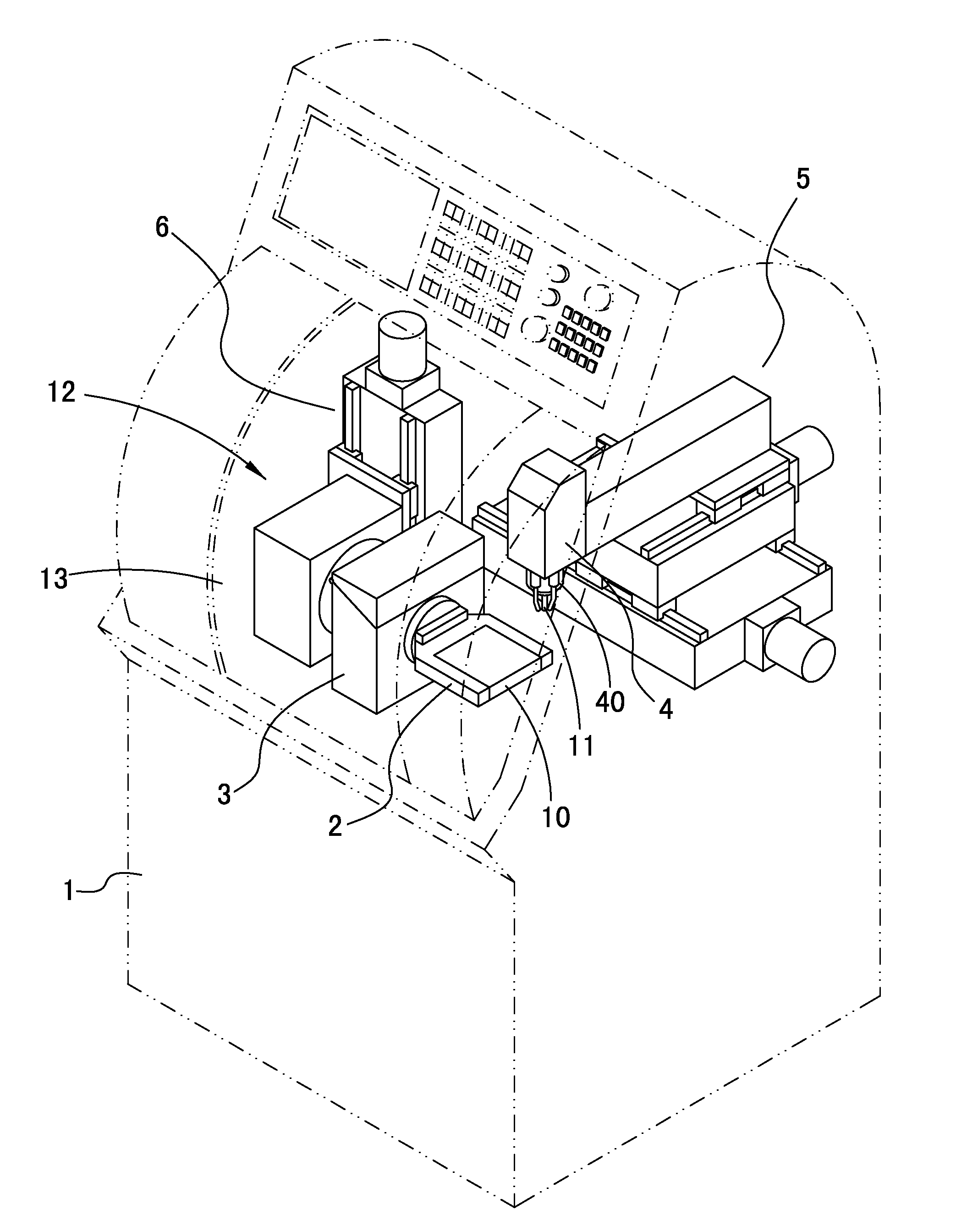
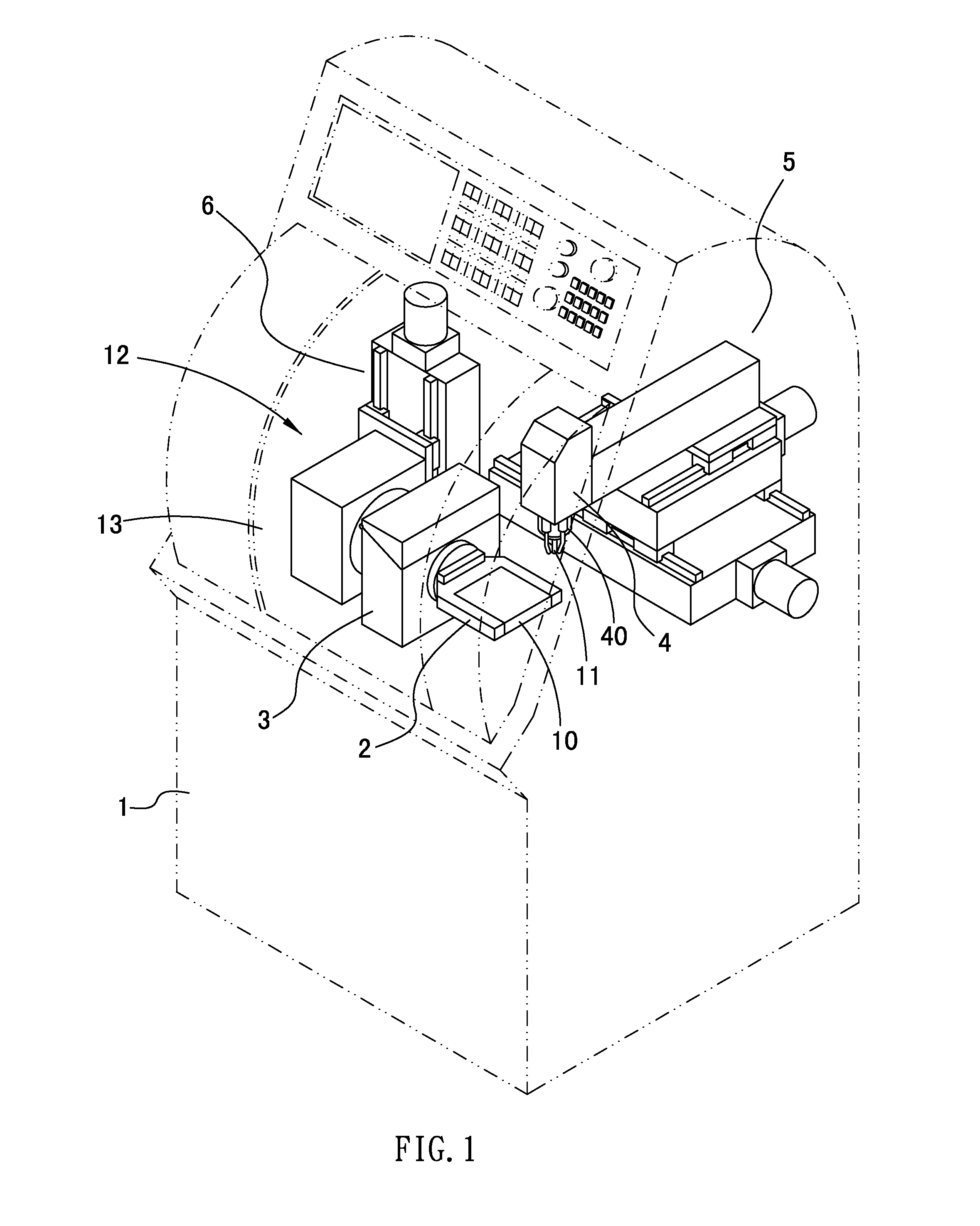
[0007]The primary object of the present invention is to provide a multi-spindle machining machine with a tool changing mechanism which can lower size and production cost and enhance tool changing efficiency.

Problems solved by technology

Conventional tool changing mechanism of a machining machine is disposed within a moving range of a carrier of a base and outside a working range of a working head, and a tool deposit is driven by another set of driving device, thus increasing size, production cost, and tool changing time.
Besides, a height of another conventional machining machine is high to increase the length and the width thereof, thereof also increasing size, production cost, and tool changing time.

Method used


Image

  • Multi-spindle machining machine with tool changing mechanism
  • Multi-spindle machining machine with tool changing mechanism
  • Multi-spindle machining machine with tool changing mechanism

Examples


second embodiment

[0041]Referring to FIG. 6, a mount 33 of the multi-spindle machining machine with a tool changing mechanism according to the present invention includes a plurality of slots 35 formed on an upper and a lower side surfaces in a line arrangement, and the rotary shaft 21 actuates the mount 33 to rotate 180 degrees / pre time.

third embodiment

[0042]Referring to FIG. 7, a mount 33 of the multi-spindle machining machine with a tool changing mechanism according to the present invention includes a plurality of slots 35 formed on an upper and a lower side surface in an annularly spaced arrangement, and the rotary shaft 21 actuates the mount 33 to an angle so that a distal end of one of the tools 11 faces upward.

[0043]With reference to FIGS. 8 and 9, the chamber 12 of the base 1 includes a dust collecting mechanism 7 to collect chips and cutting oil generating from the nozzle 41. The dust collecting mechanism 7 includes a groove 70, a tank 71, a dust collector 72, and a switching device 73, wherein

[0044]the groove 70 is disposed on a lower side of the carrier 2 of the base 1 and formed in a funnel shape to receive the chips and the cutting oil generating from a working process, and includes a pipe 74 communicating with a bottom portion thereof, the pipe 74 includes a first outlet 75 on a bottom end thereof and a second outlet ...


PUM

PropertyMeasurementUnit
lengthaaaaaaaaaa
sizeaaaaaaaaaa
heightaaaaaaaaaa

Abstract

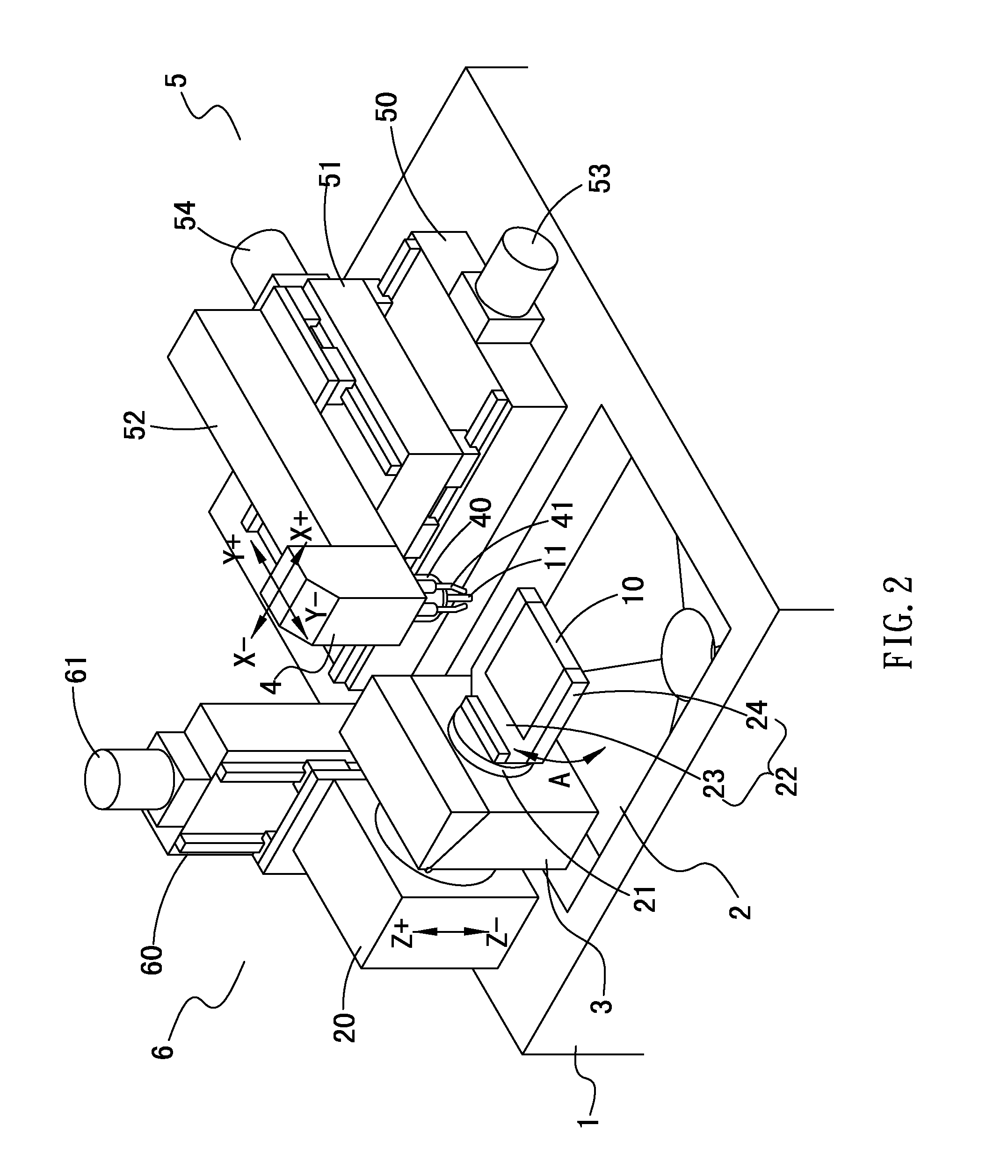
A multi-spindle machining machine with a tool changing mechanism comprising a base; a carrier including a seat to move in Z axis, a rotary shaft fixed on the seat laterally to drive the seat to rotate in A axis, and a fixing holder coupled to an end portion of the rotary shaft to fix a workpiece; a tool changing mechanism including a mount mounted to the rotary shaft to rotate with the rotary shaft and a monitor fixed on the seat to measure a length of the tool clamped on the driving spindle, and including a plurality of slots to receive the tools respectively; a working head moving above the carrier and the tool changing mechanism in X and Y axes and including a driving spindle mounted on a lower end thereof to rotate axially, and the lower end of the driving spindle allowing to engage and disengage the tool.

Description

BACKGROUND OF THE INVENTION[0001]1. Field of the Invention[0002]The present invention relates to an automatic machining machine, and more particularly to a multi-spindle machining machine with a tool changing mechanism which can lower size and production cost and enhance tool changing efficiency.[0003]2. Description of the Prior Art[0004]Conventional tool changing mechanism of a machining machine is disposed within a moving range of a carrier of a base and outside a working range of a working head, and a tool deposit is driven by another set of driving device, thus increasing size, production cost, and tool changing time.[0005]Besides, a height of another conventional machining machine is high to increase the length and the width thereof, thereof also increasing size, production cost, and tool changing time.[0006]The present invention has arisen to mitigate and / or obviate the afore-described disadvantages.SUMMARY OF THE INVENTION[0007]The primary object of the present invention is t...

Claims


Application Information

Patent Timeline
Patent Type & Authority Applications(United States)
IPC IPC(8): B23B39/16B23C1/10
CPCB23Q3/15706B23Q11/0046B23Q11/0053Y10T483/115Y10T483/11Y10T409/304088Y10T483/136Y10T483/1705Y10T409/304032Y10T483/1795Y10T483/14Y10T483/138
Inventor SHIH, CHENG HSIU
Owner SHENQ FANG YUAN TECH
Learn More