
Superconductive rotor, superconductive rotating machine and superconductive rotating-machine system

a technology of rotating machine and superconducting rotor, which is applied in the direction of superconductor devices, mechanical devices, synchronous motors, etc., can solve the problems of efficiency and speed control disadvantages, and achieve the effect of satisfying heat dissipation performance upon heat generation, large current capacity, and easy introduction into the sta

Active Publication Date: 2011-04-14
KYOTO UNIV
View PDF11 Cites 18 Cited by
  • Summary
  • Abstract
  • Description
  • Claims
  • Application Information

AI Technical Summary

Benefits of technology

[0034]The superconductive rotating machine of the present invention has the superconductive squirrel-cage winding formed using a superconductive wire, rather than a superconductive bulk material, and therefore offers satisfactory heat dissipation performance upon heat generation.
[0035]In addition, the superconductive bulk material has a large current capacity, and therefore is difficult to be in the state of magnetic flux flow once it is brought into the superconductive state. On the other hand, the superconductive squirrel-cage winding of the superconductive rotating machine according to the present invention is made using a superconductive wire having a small current capacity, and therefore it can be readily brought into the state of magnetic flux flow. Thus, even when the superconductive squirrel-cage winding is in the superconductive state without trapping magnetic flux, the superconductive rotating machine of the present invention can achieve synchronous rotation by temporarily bringing the superconductive squirrel-cage winding into the state of magnetic flux flow and thereby allowing easy trapping of interlinkage magnetic flux.

Problems solved by technology

The induction motor is widely used because of, for example, its simplified structure, easy maintenance and low cost, but it has disadvantages in terms of efficiency and speed control.

Method used


Image

  • Superconductive rotor, superconductive rotating machine and superconductive rotating-machine system
  • Superconductive rotor, superconductive rotating machine and superconductive rotating-machine system
  • Superconductive rotor, superconductive rotating machine and superconductive rotating-machine system

Examples


Embodiment Construction

[0053]Hereinafter, a preferred embodiment of the present invention will be described with reference to the drawings.

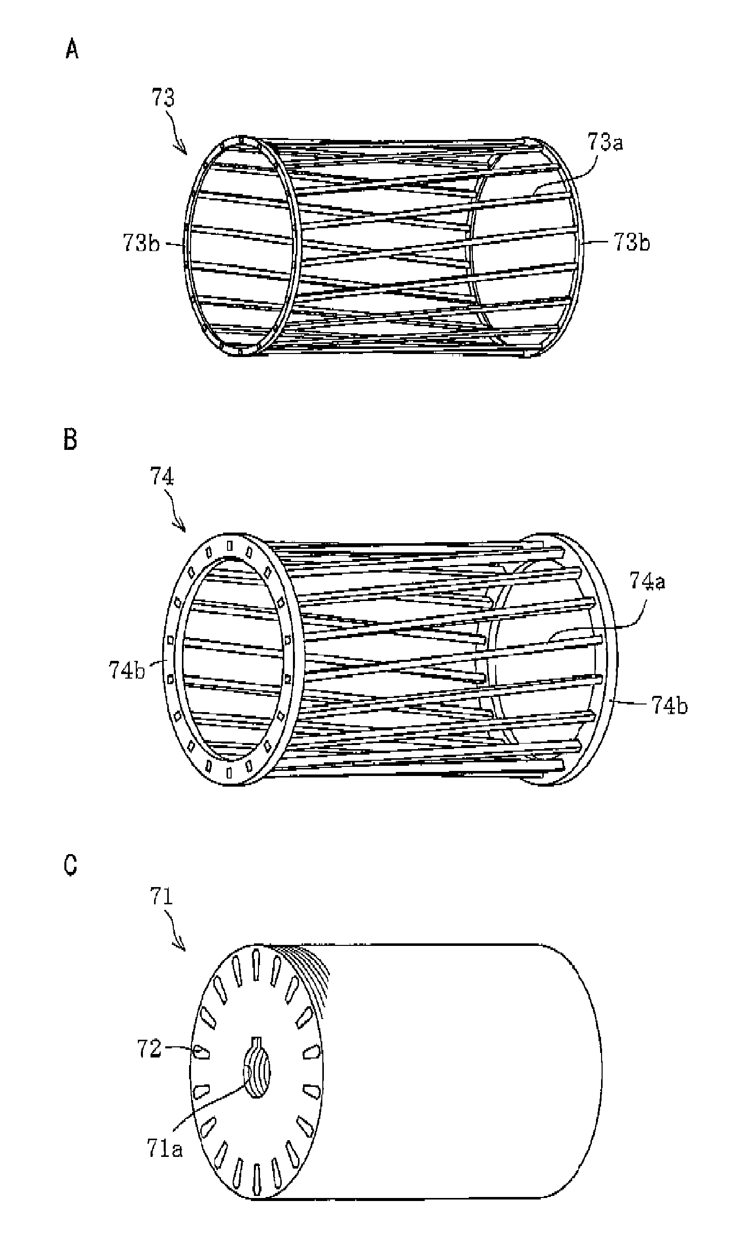
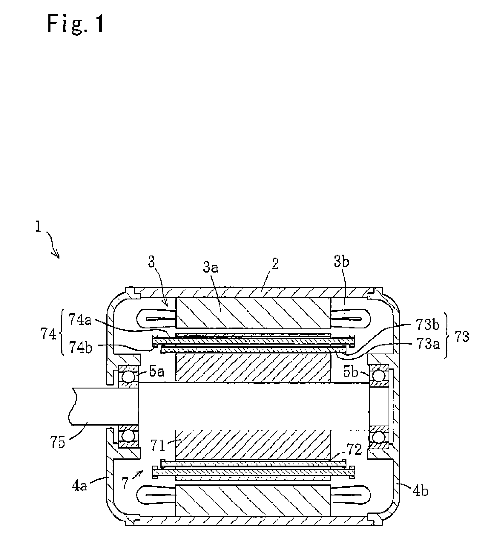
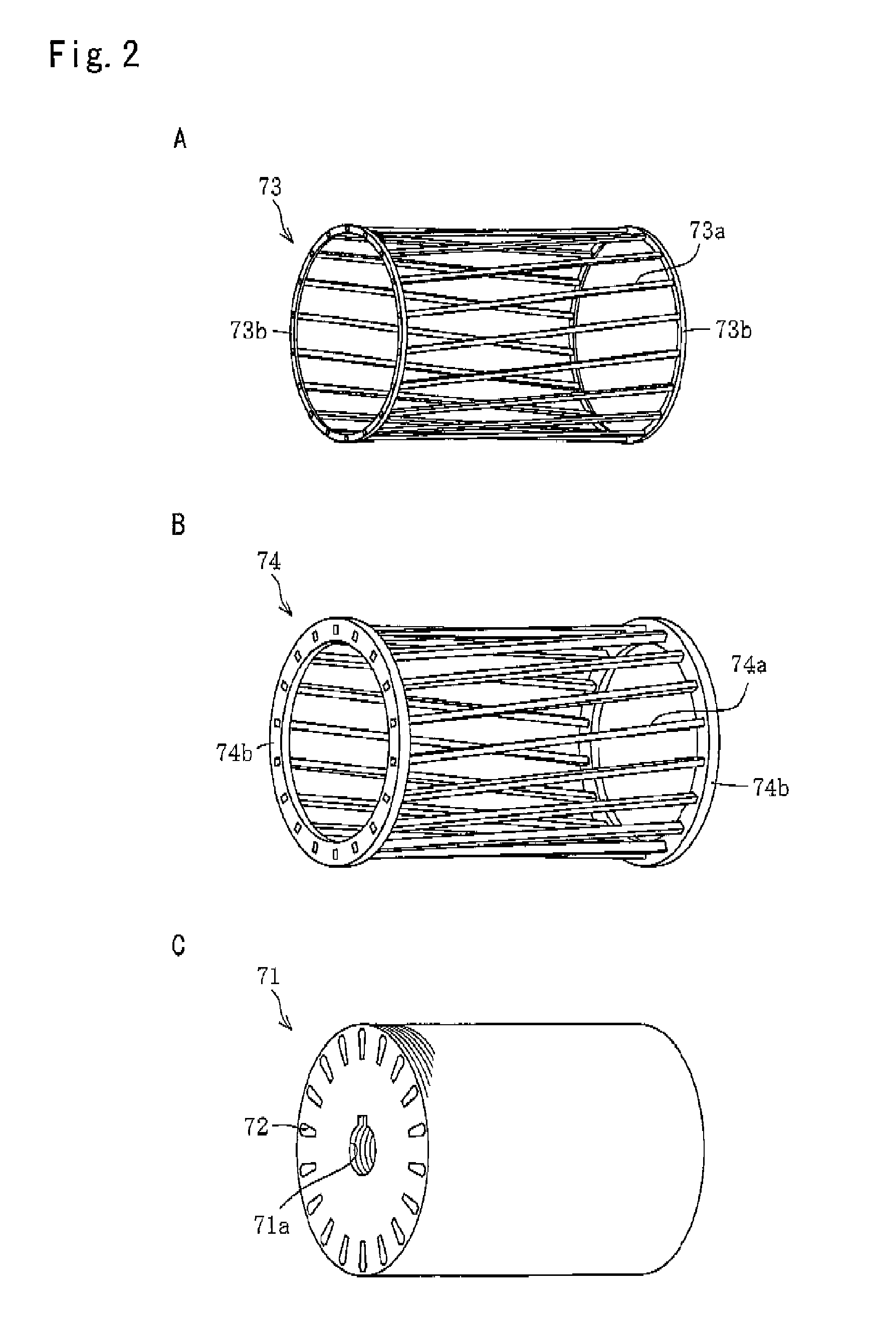
[0054]FIG. 1 is a longitudinal cross-section end view of a superconductive electric motor according to the present invention. FIG. 2 provides views (A), (B) and (C) respectively illustrating a superconductive squirrel-cage winding, a normally conductive squirrel-cage winding and a rotor core of the superconductive electric motor in FIG. 1. FIG. 3 is a schematic view illustrating in horizontal cross-section a superconductive wire included in the superconductive squirrel-cage winding in FIG. 2. FIG. 4 is a horizontal cross-sectional view of a rotor of the superconductive electric motor in FIG. 1, and FIG. 5 is a block diagram illustrating a superconductive electric motor system to which the superconductive electric motor in FIG. 1 is applied.

[0055][Superconductive Electric Motor]

[0056]As shown in FIG. 1, the superconductive electric motor (superconductive rotating machin...


PUM


Abstract

The main problem to be solved by the invention is to provide a superconductive rotor, a superconductive rotating machine and a superconductive rotating-machine system which are capable of inductive and synchronous rotation while employing the induction machine configuration and also offer satisfactory heat dissipation performance, stability under an excessive load, and easy magnetic flux trap for synchronous rotation. To solve the problem, the invention provides a superconductive rotor, as shown in FIG. 1, including a superconductive squirrel-cage winding formed by superconductive wires having a plurality of superconductive wires covered with a highly conductive metal; a normally conductive squirrel-cage winding formed by a normally conductive material; a cylindrical rotor core having a plurality of slots for accommodating the rotor bars of both of the squirrel-cage windings; and a rotor shaft coaxially provided to the rotor core, wherein, when the superconductive squirrel-cage winding is in a non-superconductive state, rotations are mainly made by an induced torque generated on the normally conductive squirrel-cage winding due to a rotating magnetic field and, when the superconductive squirrel-cage winding is in a superconductive state, rotations are mainly made by a synchronous torque generated by the superconductive squirrel-cage winding trapping magnetic flux of the rotating magnetic field.

Description

TECHNICAL FIELD[0001]The present invention relates to superconductive rotors, superconductive rotating machines and superconductive rotating-machine systems.BACKGROUND ART[0002]As electric equipment, rotating machines are classified as direct- and alternating-current machines. Among them, the alternating-current machines generate alternating-current power by receiving mechanical power or generate mechanical power by receiving alternating-current power, and they are mainly classified as induction and synchronous machines.[0003]The induction machine, e.g., an induction motor, rotates by generating an induced torque on a rotor with a rotating magnetic field generated by applying alternating-current voltage to a stator winding. The induction motor is widely used because of, for example, its simplified structure, easy maintenance and low cost, but it has disadvantages in terms of efficiency and speed control.[0004]The synchronous machine, e.g., a synchronous motor, rotates by a rotor, wh...

Claims


Application Information

Patent Timeline
IPC IPC(8): H02K19/14
CPCH02K17/14Y02E40/625H02K55/04Y02E40/60
Inventor NAKAMURA, TAKETSUNE
Owner KYOTO UNIV
Learn More