Eureka AIR delivers breakthrough ideas for toughest innovation challenges, trusted by R&D personnel around the world.

Light source device

Active Publication Date: 2011-04-14
SEIKO EPSON CORP
View PDF3 Cites 6 Cited by
  • Summary
  • Abstract
  • Description
  • Claims
  • Application Information

AI Technical Summary

Benefits of technology

[0025]According to the invention, since the other end of the trigger wire wound around the outer periphery of the sealing portion is disposed to the proximity guide portion formed at a position away from the light emitting portion of the light emitting tube and is not in contact with the light emitting portion, the rate of elongation at the other end by thermal expansion is small.
[0026]Further, by bringing the trigger wire at the intermediated portion in a stretched state into contact with the surface of the light emitting portion of the light emitting tube and fixing the other end of the trigger wire in this state by winding around and securing to the proximity guide portion such as a concave groove or an insertion hole formed to the outer peripheral surface of the sealing portion, the extent that the trigger wire is spaced apart from the surface of the light emitting tube by thermal expansion is suppressed to the minimum.
[0027]Further, since the end of the trigger wire connected to one electrode assembly is wound around and secured to the proximity guide portion such as the concave groove or the insertion hole formed to the outer periphery of the sealing portion for securing the other electrode assembly, the distance between the trigger wire and the other electrode assembly is shortened by so much as a length corresponding to the depth of the proximity guide portion to increase the electric field intensity between both of them.
[0028]In this case, as the area for the trigger wire i

Problems solved by technology

However, since the high pressure discharge lamp of this type has no good starting performance in a cold state or re-starting performance in a hot state, it involved a problem that the rising time of the liquid crystal projector or the projection television was retarded.
However, when the starting voltage of the high pressure discharge lamp is increased, since a sufficient insulation distance has to be ensured between wirings constituting a lighting circuit, this involves a problem of increasing the size of the lighting circuit to enlarge the installation space for the light source device, and the size of the liquid crystal projector, etc., can not be decreased.
Further, in a case where the pulse voltage of the high voltage pulse applied to the starting voltage is high, noises that cause erroneous operation to the electric circuits such as in a liquid crystal projector may possibly be generated.

Method used


Image

  • Light source device
  • Light source device
  • Light source device

Examples


example 1

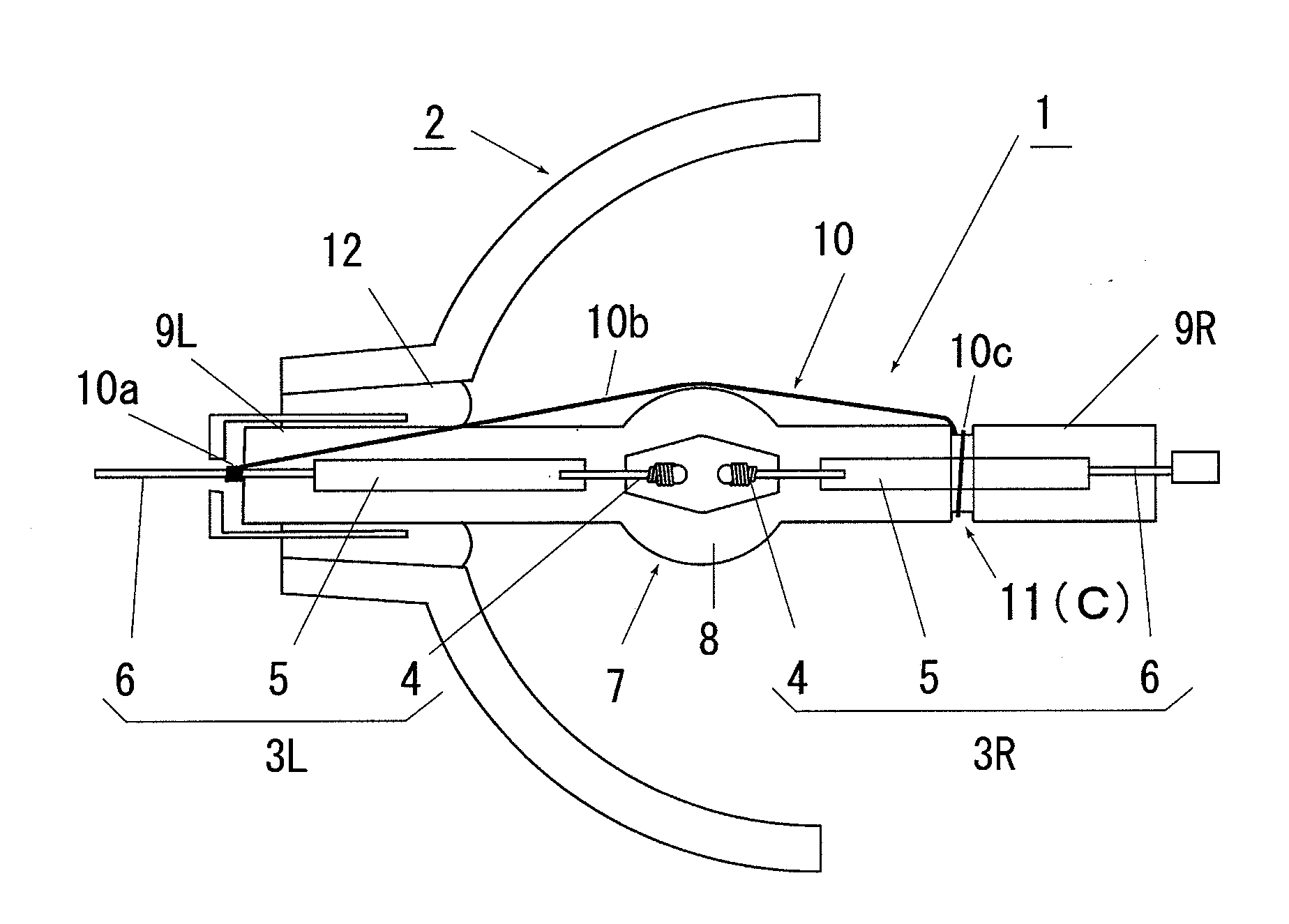
[0047]A light source device in FIG. 1 is a lamp having a reflection mirror for a liquid crystal projector in which a high pressure discharge lamp 1 comprising a short arc type high pressure mercury vapor discharge lamp having a rated lamp power of 150 W and a concave surface reflection mirror 2 with a reflection surface forming a parabolic surface are integrated. In the high pressure discharge lamp 1, a pair of electrode assemblies 3R,3L each having a tungsten electrode 4 connected by way of a metal foil 5 to a power supply lead 6 are inserted on both ends of a light emitting tube 7 comprising a quartz glass tube such that the electrodes 4, 4 are opposed to each other being kept at an inter-electrode distance of about 1.1 mm in a light emitting portion 8 formed in the central portion of the light emitting tube 7 and sealed at both ends in a pair of sealing portions 9R, 9L for air tightly sealing the both ends thereof.

[0048]In the light emitting tube 7 of the high pressure discharge ...

example 2

[0076]FIG. 8 is an entire view showing another example of a light source device according to the invention and the constitution is identical with the light source device of FIG. 1 excepting that an auxiliary-reflection mirror 13 is disposed to a high pressure discharge lamp 1 and except for the mounting structure of a trigger wire 10.

[0077]In the high pressure discharge lamp 1 of FIG. 8, an auxiliary-reflection mirror 13 for reflecting a light emitted from a light emitting portion 8 of a light emitting tube 7 to an opening 14 of the concave reflection mirror 2 toward the light emitting portion 8 is mounted being situated between the light emitting portion 8 and a concave groove 11 as a proximity guide portion C for winging and securing the other end 10c of a trigger wire 10 to the outer periphery of a sealing portion 9R of the light emitting tube 7 formed with the concave groove 11 and a spiral guide groove 15c is foamed from the mounting position of the auxiliary-reflection mirror ...

example 3

[0085]FIG. 11 is an explanatory view showing a main portion of other light source device according to the invention.

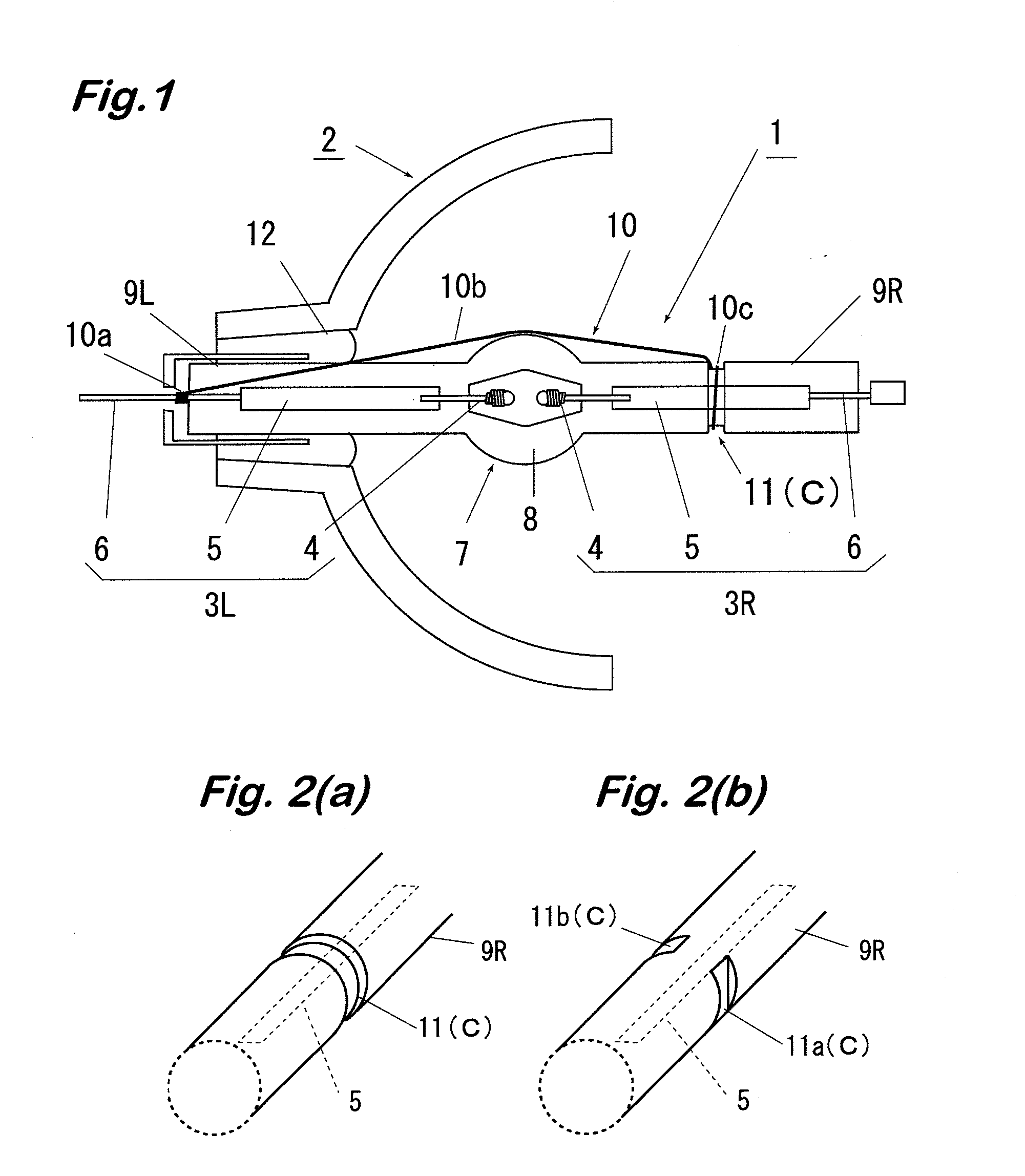
[0086]The light source device of this embodiment is identical with the light source device shown in FIG. 1 excepting that a trigger wire insertion hole 17 of about 1 mm diameter is bored instead of the concave groove 11 as a proximity guide portion C formed to the sealing portion 3R of the high pressure discharge lamp 1.

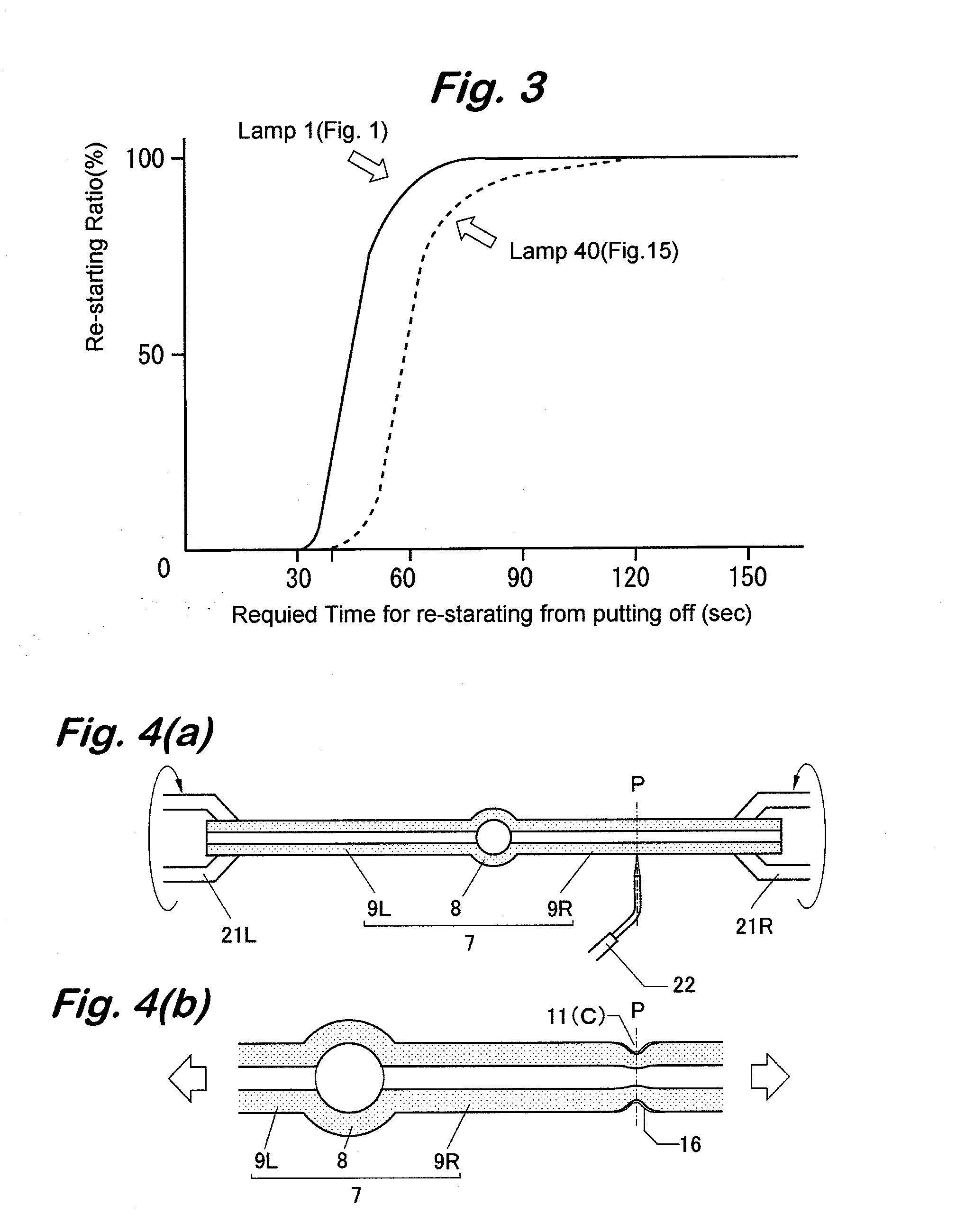
[0087]As shown in FIG. 12, the trigger wire insertion hole 17 is perforated by at first fixing both ends of a light emitting tube 7 having electrode assemblies 3R, 3L sealed therein to chucks 21R, 21L of a glass lathe and, without rotating them, irradiating a laser light from a laser 28 the optical axis thereof being set so as not to cross a metal foil 5 of the electrode assembly 3R at a trigger wire winding and securing position P of the sealing portion 9R.

[0088]The thus perforated trigger wire insertion hole 17 may be perforated in a direction perpend...


PUM


Abstract

The invention relates to a light source device having a high-voltage discharge lamp (1) on which a trigger line (10) for triggering the lamp is attached. The high-voltage discharge lamp (1) is formed such that an arc tube (7) having a pair of substantially cylindrical sealing portions (9R, 9L) formed on both sides in the longitudinal direction with a light emitting portion (8) in between is sealed with electrode assemblies (3R, 3L). The trigger line (10) is formed such that its one end (10a) is connected to a power supply lead (6), which is of the electrode assembly (3L) and protruded from the one sealing portion (9L), and its other end (10c) is wound around the outer circumference of the other sealing portion (9R). In the light source device, in order to drastically improve the performance for triggering and retriggering the lamp (1), a vicinity guide portion (C) including a hollow groove (11) and an insert opening (17) is formed on a cylindrical portion of the other sealing portion (9R) at a position away from the light emitting portion (8). The vicinity guide portion (C) allows the trigger line (10) to be disposed at a distance shorter than the distance from the electrode assembly to the outer circumference surface of the cylindrical portion.

Description

TECHNICAL FIELD[0001]The present invention concerns a light source device used as a backlight for liquid crystal projectors or projection televisions and it particularly relates to a light source device provided with a trigger wire to a high pressure discharge lamp as a light source for enhancing the starting performance thereof.BACKGROUND[0002]Along with decrease in the size and the thickness of liquid crystal projectors and projection televisions, decrease in the size is also intended for the light source device assembled in such equipments, for example, by using a short arc type high pressure mercury vapor discharge lamp capable of obtaining a high luminance emission in a small size. However, since the high pressure discharge lamp of this type has no good starting performance in a cold state or re-starting performance in a hot state, it involved a problem that the rising time of the liquid crystal projector or the projection television was retarded.[0003]Accordingly, while it is ...

Claims


Application Information

Patent Timeline
IPC IPC(8): H01K1/30H01J61/30F21Y101/00
CPCH01J61/547G03B21/2026H01J61/86H01J61/54H01J61/36
Inventor UEHARA, SUMIONAGASE, TOORUMASEKI, KYOUICHINAKAJIMA, KOUICHIOOKAHARA, MAKOTOKOMATSU, YOSHIAKIHIROTA, MASAKIKAMIMURA, MASAKI
Owner SEIKO EPSON CORP
Why Eureka
Eureka Blog
Learn More