Eureka AIR delivers breakthrough ideas for toughest innovation challenges, trusted by R&D personnel around the world.

Coating material, coating film, and gas insulated switchgear

Active Publication Date: 2019-05-16
MITSUBISHI ELECTRIC CORP
View PDF0 Cites 1 Cited by
  • Summary
  • Abstract
  • Description
  • Claims
  • Application Information

AI Technical Summary

Benefits of technology

The patent text describes a way to increase the electric field intensity at which a coating film with nonlinear resistance begins to decrease. This can be useful in various applications where controlling the resistivity of a coating film is important.

Problems solved by technology

However, during production or installation operation on site, contaminants may be mixed in the ground tank.
The electric field concentrates on the periphery of the contaminants, and therefore the contaminants get close to or stick to the central conductor, the electric field may locally increase, leading to deterioration of voltage resistance performance of the gas insulated switchgear.
Thus, a situation is prevented in which metallic contaminants float, and stick to the center conductor, leading to occurrence of flashover.

Method used


Image

  • Coating material, coating film, and gas insulated switchgear
  • Coating material, coating film, and gas insulated switchgear
  • Coating material, coating film, and gas insulated switchgear

Examples


embodiment 1

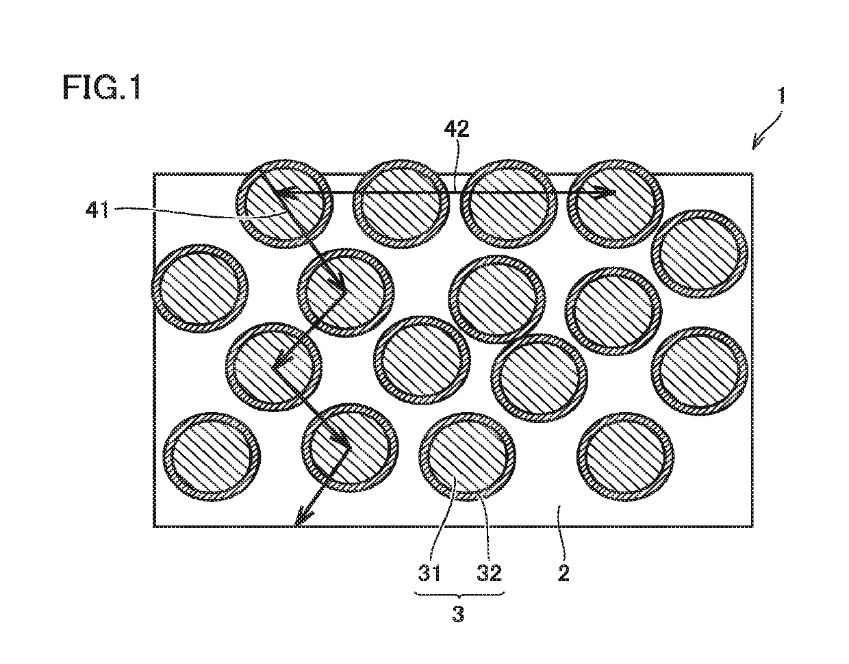
[0020]FIG. 1 is a schematic sectional view showing a configuration of a coating film according to embodiment 1. As shown in FIG. 1, a coating film 1 contains an insulating resin 2 and dispersion particles 3 dispersed in insulating resin 2, and has nonlinear resistance.

[0021]Insulating resin 2 is not particularly limited as long as it is a resin which is used for a coating material, and has insulation quality, and insulating resin 2 may be liquid, or solid as long as it is soluble in a solvent. As insulating resin 2, for example, various thermosetting resins, thermoplastic resins, thermosensitive resins and the like can be used. As the solvent, mention is made of at least one solvent selected from alcohols, aliphatic (or aromatic) carboxylic acid esters, ketones, ethers, ether esters, aliphatic (or aromatic) hydrocarbons and the like.

[0022]Examples of the thermosetting resin include epoxy resins, phenol resins, melamine resins, unsaturated polyester resins and polyamide resins.

[0023]...

example 1

[0067]First, an epoxy resin (36% by volume), zinc oxide particles (number average particle diameter: 55 μm) (38% by volume) covered with a resin layer (average thickness: 0.7 epoxy resin), and a modified urea-type anti-settling agent (product name: BYK-410, manufactured by BYK Japan K.K.) (2.0% by volume) were mixed to obtain a mixture. Next, a quick-drying thinner (specifically, EPONICS THINNER B manufactured by Dai Nippon Toryo Company, Limited) (24% by volume) was added to the mixture, and the resulting mixture was stirred to obtain a coating material. The parenthesized ratio is a ratio to the total amount of the coating material. The obtained coating material was applied onto a circular aluminum plate, and cured to prepare a coating film of Example 1.

example 2

[0068]Except that an anti-settling agent was not added, the same procedure as in Example 1 was carried out to prepare a coating film of Example 2. In this example, the content of the quick-drying thinner was increased to 26% by volume instead of adding the anti-settling agent.


PUM

PropertyMeasurementUnit
Thicknessaaaaaaaaaa
Thicknessaaaaaaaaaa
Thicknessaaaaaaaaaa

Abstract

A coating material of the present invention includes an insulating resin, and dispersion particles dispersed in the insulating resin. The dispersion particle includes a core particle containing zinc oxide as a main component and having nonlinear resistance, and a resin layer covering the surface of the core particle and having an average thickness being less than or equal to 5.0 μm. The coating material of the present invention is a coating material for coating an inner surface of a ground tank of a gas insulated switchgear.

Description

TECHNICAL FIELD[0001]The present invention relates to a coating material, a coating film and a gas insulated switchgear.BACKGROUND ART[0002]In a gas insulated switchgear (GIS), a metallic tank at a ground potential (ground tank) contains a center conductor to which a high voltage is applied, and a space between the ground tank and the center conductor is filled with an insulating gas to secure insulation performance.[0003]However, during production or installation operation on site, contaminants may be mixed in the ground tank. When millimeter-sized metallic contaminants are mixed in the ground tank, the metallic contaminants are charged under the influence of an electric field generated from the center conductor to which a high voltage is applied, so that an electrostatic force is exerted in a floating direction from the inner bottom surface of the ground tank. When the electrostatic force is greater than the gravity acting on the contaminants, the contaminants float, and move towa...

Claims


Application Information

Patent Timeline
IPC IPC(8): C09D163/00C09D7/62C09D7/40C09D7/45C09D7/20H02B13/045
CPCC09D163/00C09D7/62C09D7/69C09D7/45C09D7/20H02B13/045H02G5/065C08K2003/2296C09D201/00
Inventor SATO, SATORUYASUDA, NAOKIYOKOMURA, NOBUOKAWANO, RYOKOYOSHIMURA, MANABUNAKAUCHI, SHINICHIRO
Owner MITSUBISHI ELECTRIC CORP
Why Eureka
Eureka Blog
Learn More