Information storage/readout device for use in continuously manufacturing system for liquid-crystal display elements, and method and system for producing the same

a technology of information storage and readout device, which is applied in the direction of controlling lamination, instruments, other domestic articles, etc., can solve the problems of inability to adapt the method taught in the patent document 3 directly to the manufacturing process, and the inability to obtain finished liquid crystal display elements. achieve the effect of improving production yield and improving product accuracy and manufacturing speed

Inactive Publication Date: 2011-04-14
NITTO DENKO CORP
View PDF9 Cites 24 Cited by
  • Summary
  • Abstract
  • Description
  • Claims
  • Application Information

AI Technical Summary

Benefits of technology

[0031]The VA-type and IPS-type liquid-crystal panels are advantageous over TN-type liquid-crystal panels from the viewpoint of manufacture in that there is no restriction in the VA and IPS-types that two polarizing sheets are required to be laminated to respective ones of front and rear surfaces of the liquid-crystal panel in 45 degrees oblique with respect to the polarization axis of the polarizing sheet on the respective sides of the liquid-crystal display element, as experienced in the manufacture of TN-type liquid-crystal panels, due to the viewing angle characteristics inherent to the orientation of the liquid-crystal. Therefore, it is possible to carry out a process for continuously manufacturing liquid-crystal display elements using the VA-type and IPS-type liquid-crystal panels, while feeding a continuous optical film laminate, by continuously laminating the polarizing composit

Problems solved by technology

As the individualized sheets are flexible, they tend to be bowed or warped on their edges, and thus it is a serious technical impediment in lamination with liquid-crystal panels.
In the manufacturing process of TN-type liquid-crystal display elements, it is impossible to obtain finished liquid-crystal display elements simply by sequentially laminating the sheets formed in the sequential punching or cutting process to respective ones of a plurality of liquid-crystal panels in a subsequent process.
At any rate, the above methods do not provide any noticeable improvement over the method of using individualized sheets.
Therefore, the method taught by the Patent Document 3 cannot be applied directly to a manufacturing process adapted to perform steps of continuously providing a plurality of polarizing composite film sheets from a continuous optical film laminate and laminating the respective sheets to respective ones of the liquid-crystal panels comprising VA-type or IPS-type liquid-crystal.
Flexible individualized sheets tend to be bowed or warped due to curves or distortion of their edges, and thus it is a serious technical impediment to accuracy and speed in registration and lamination with liquid-crystal panels.
However, the mainstream of manufacture of liquid-crystal display elements is still based on the manufacturing technology utilizing individualized sheets, due to the following technical problems.
In manufacturi

Method used


Image

  • Information storage/readout device for use in continuously manufacturing system for liquid-crystal display elements, and method and system for producing the same
  • Information storage/readout device for use in continuously manufacturing system for liquid-crystal display elements, and method and system for producing the same
  • Information storage/readout device for use in continuously manufacturing system for liquid-crystal display elements, and method and system for producing the same

Examples


first embodiment

[0092](Method and System for Information Storage / Readout Device )

[0093]FIG. 6 is a schematic diagram showing a method and system for creating the slitting position information 80, and producing the roll R of the continuous inspected optical film laminate provided with the identification means or indicia 20 associated with the slitting position information 80 stored in the information storage medium 800. FIG. 7 is a flowchart showing the production process in the method and system for producing the roll R, illustrated in FIG. 6.

[0094]According to the first embodiment illustrated in FIG. 6, there is provided an information storage / readout device 500 which has a polarizer manufacturing line 510 for forming a continuous polarizer, a protective film manufacturing line 520 for forming a continuous protective film to be laminated on the continuous polarizer, a polarizing composite film manufacturing line 530 for laminating the continuous protective film on the continuous polarizer through ...

second embodiment

[0104](Method and System for Producing Information Storage / Readout Device )

[0105]FIG. 8 is a schematic diagram showing a method and system for creating the slitting position information 80, and producing the roll R of the continuous inspected optical film laminate provided with the identification means or indicia 20 associated with the slitting position information 80 stored in the information storage medium 800, using a roll R′ of a continuous provisional optical film laminate R′. FIG. 9 is a flowchart showing the production process in the method and system for producing the roll R, illustrated in FIG. 8.

[0106]An information storage / readout device 500′ according to the second embodiment illustrated in FIG. 8 will be described by designating parts with identical reference characters to those in the system 500 according to the first embodiment except those different from the parts in the system 500. In the system 500′ according to the second embodiment, a roll R′ of a preliminarily p...

third embodiment

[0116]FIG. 10 is a schematic diagram showing the relationship between the identification means or indicia 20 read by the identification reading unit 120 and the slitting position information 80 read out from the information storage medium 800 or the storage device 420 in accordance with the identification means or indicia 20, in the system for continuously manufacturing liquid-crystal display element illustrated in FIG. 4, using an information storage / readout device according to one embodiment of the present invention, which comprises the information storage medium 800 storing therein the slitting position information 80 created for the continuous inspected optical film laminate 10 by the production system for the roll R, illustrated in FIG. 6 or 8, and the roll R of the continuous inspected optical film laminate 10 provided with the identification means or indicia 20 associated with the slitting position information 80. As the present invention, a method and system for continuously...


PUM


Abstract

An information storage/readout device for use in a system for continuously manufacturing liquid-crystal display elements comprises an information storage medium which stores therein slitting position information created based on the position of a defect detected by an inspection of a continuous polarizing composite film included in a continuous optical film laminate including a continuous polarizing composite film formed with an adhesive layer and a continuous carrier film releasably laminated on the adhesive layer, to indicate defective-polarizing-sheet slitting positions defining a defective or defect-containing polarizing sheet, and normal-polarizing-sheet slitting positions defining a normal or defect-free polarizing sheet, in the continuous inspected optical film laminate, and a roll of the continuous inspected optical film laminate which is provided with an identification indicia. In continuous manufacturing of liquid-crystal display elements, the present invention can dramatically enhance product accuracy and manufacturing speed and drastically improve product yield.

Description

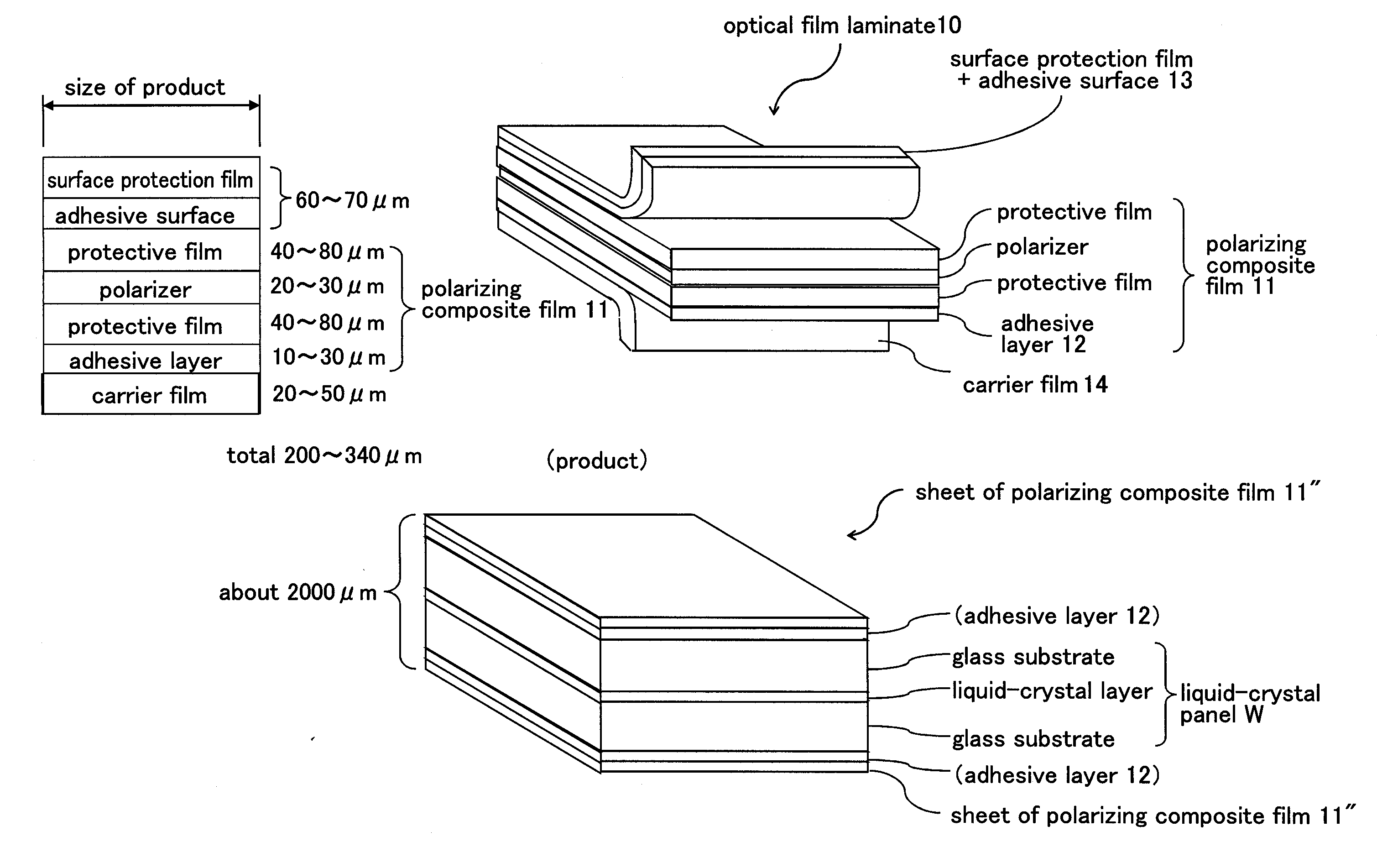
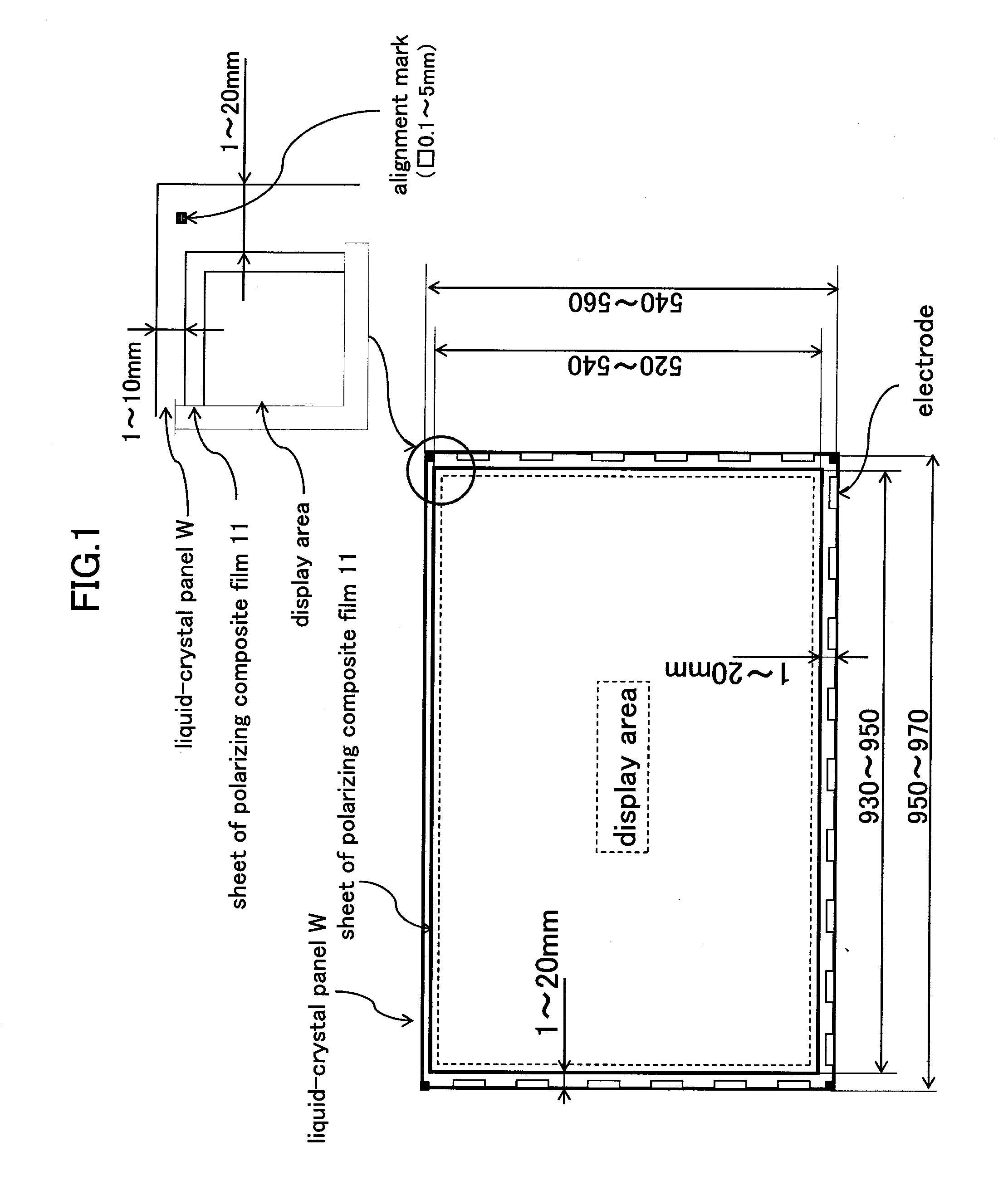
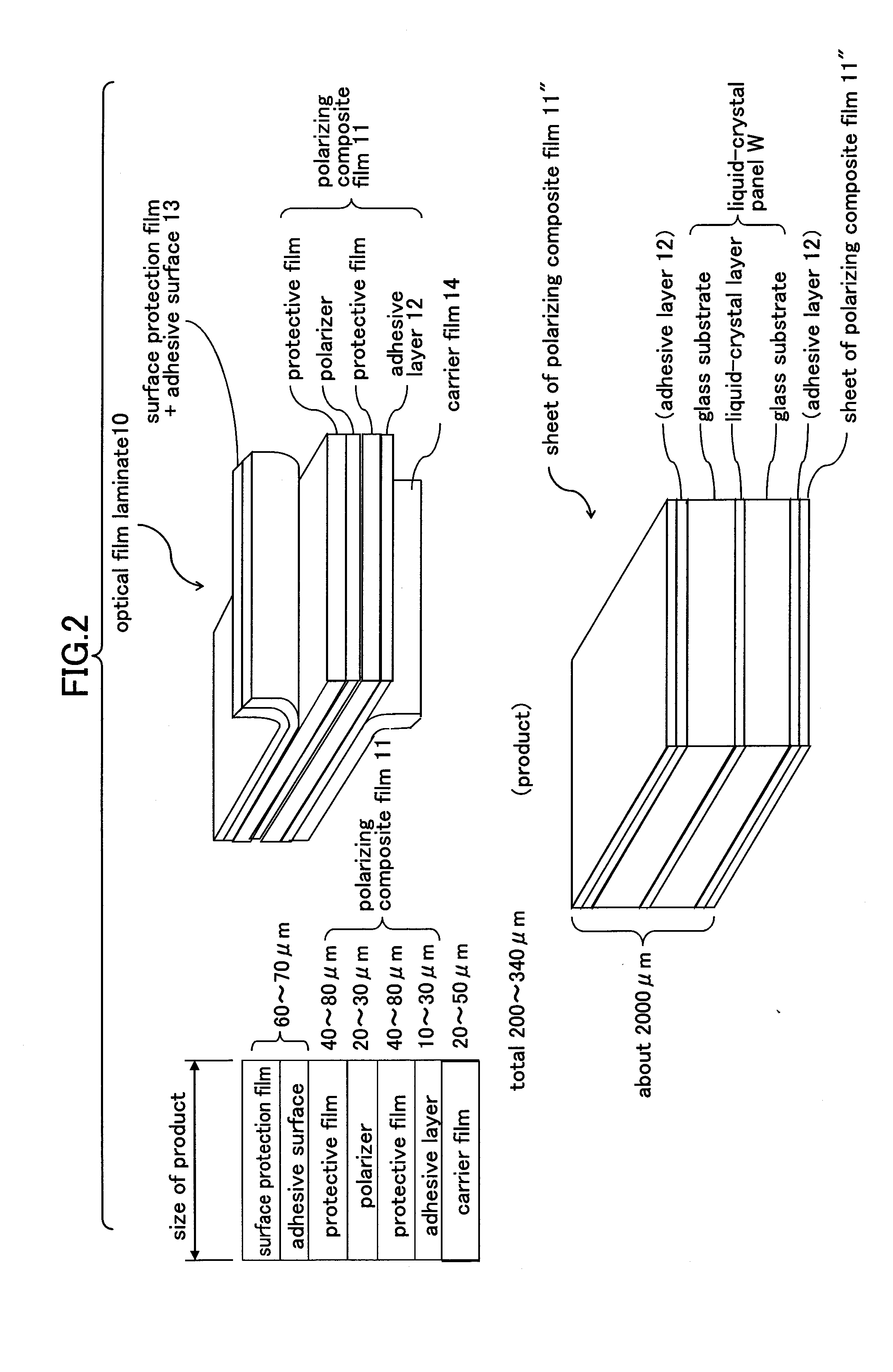
TECHNICAL FIELD[0001]The present invention relates to an information storage / readout device for use in a continuous manufacturing system for liquid-crystal display elements, wherein the continuous manufacturing system is configured to work with a roll of a continuous optical film laminate which comprises a continuous polarizing composite film including an adhesive layer and having a width conforming to a long or short side of a liquid-crystal panel formed in a given size, and a continuous carrier film releasably laminated on the adhesive layer, the system being operative to form a plurality of slits in the continuous optical film laminate fed out from the roll, along a direction perpendicular to a longitudinal direction thereof, to allow a plurality of polarizing sheets each having a given length corresponding to the long or short side of the liquid-crystal panel to be sequentially cut from the continuous optical film laminate and laminated to respective ones of a plurality of liqui...

Claims


Application Information

Patent Timeline
IPC IPC(8): G02F1/13
CPCB32B41/00G01N21/896B32B2457/202
Inventor KIMURA, KOUJIKITADA, KAZUOYURA, TOMOKAZUKOSHIO, SATORUSHIMANOE, FUMIHITONAKAZONO, TAKUYA
Owner NITTO DENKO CORP
Why Eureka
Try Eureka