Method and device for diffuse excitation in imaging

a diffuse excitation and imaging technology, applied in the field of diffuse optical imaging, can solve the problems of affecting the resolution of images, damage to the medium, and the temptation to inject high laser energy into, so as to facilitate and improve the reconstruction of the optical properties of the medium, improve the effect of signal collection

Active Publication Date: 2011-04-14
COMMISSARIAT A LENERGIE ATOMIQUE ET AUX ENERGIES ALTERNATIVES
View PDF25 Cites 40 Cited by
  • Summary
  • Abstract
  • Description
  • Claims
  • Application Information

AI Technical Summary

Benefits of technology

[0023]In particular a signal collecting fibre, whether a fluorescence or diffusion signal, can be inserted permanently or in a housing inside the diffusing matter of the mass or matrix. In this case, improved efficacy of signal collection is ascertained compared with the case in which this fibre is located outside the coupling device of the invention.
[0024]The effect of using a matrix is to distance the boundary of the medium from the ends of the excitation fibre(s) and / or collection fibre(s), which limits the perturbation related to edge effects. With a thick matrix, whose thickness (along a direction substantially perpendicular to the bearing surface) exceeds a few cm, e.g. greater than 3 cm or 5 cm, the influence of the edges becomes negligible; the conditions are then close to those of an infinite medium which subsequently facilitates and improves the reconstruction of the optical properties of the medium.

Problems solved by technology

Whatever the technique used, to achieve better sensitivity there is a possible temptation to inject high laser energy into the examined medium.
However a problem of damage to this medium arises above a certain energy density.
However, in addition to the fact that the tissues will evacuate heat less easily, the resolution of the image will be deteriorated on and after a fibre 10 diameter of the order of 1 mm.
Another problem is the problem of sensitivity: it is desired to achieve the best collection of the photons emanated by the examined medium 11.
Another problem relates to edge effects which hamper reconstruction, these being difficult to model accurately.
It is therefore ascertained that the boundaries of the medium are a source of error when reconstructing the properties of the medium.

Method used


Image

  • Method and device for diffuse excitation in imaging
  • Method and device for diffuse excitation in imaging
  • Method and device for diffuse excitation in imaging

Examples


Embodiment Construction

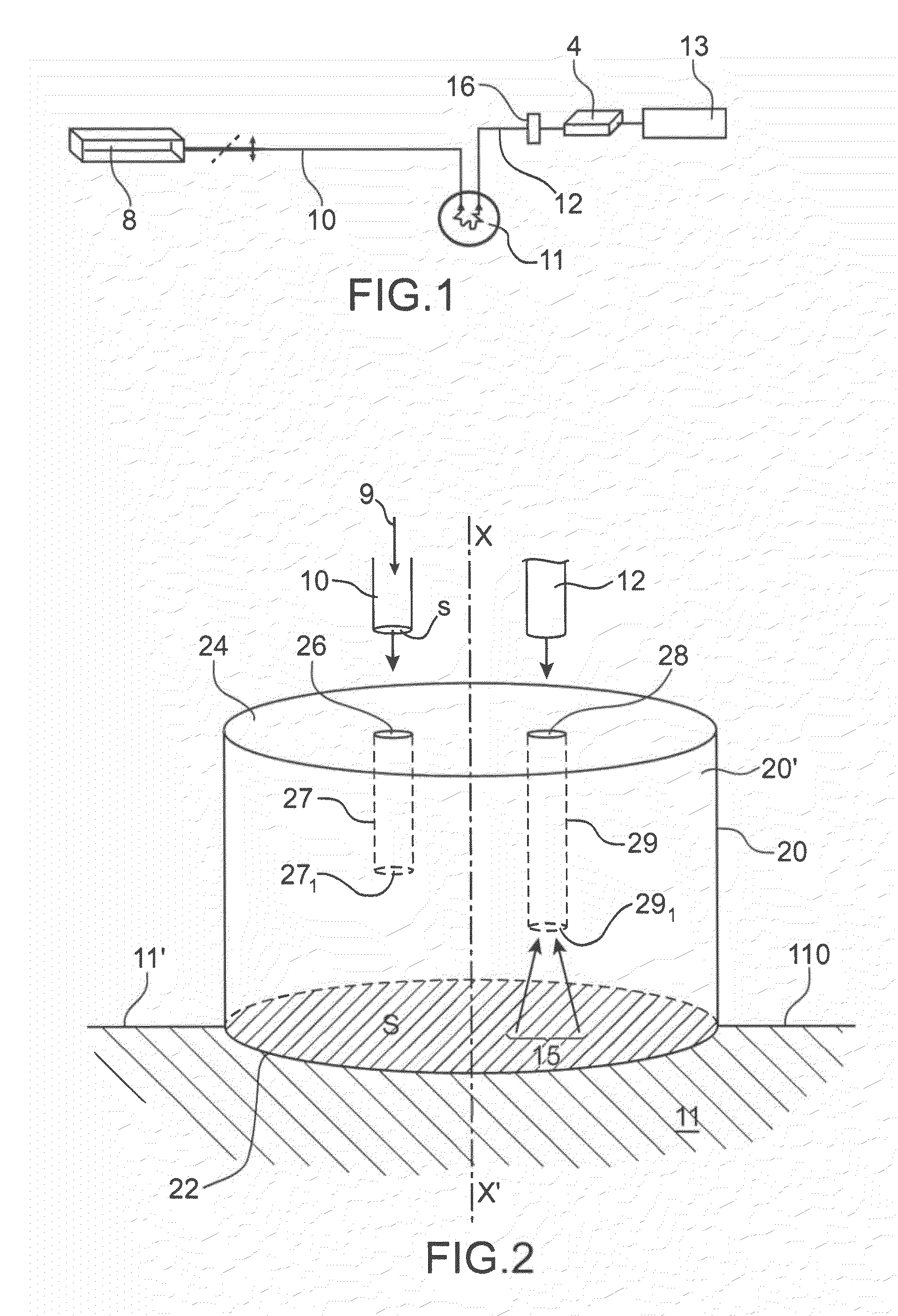
[0067]A first example of an embodiment of the invention is given FIG. 2.

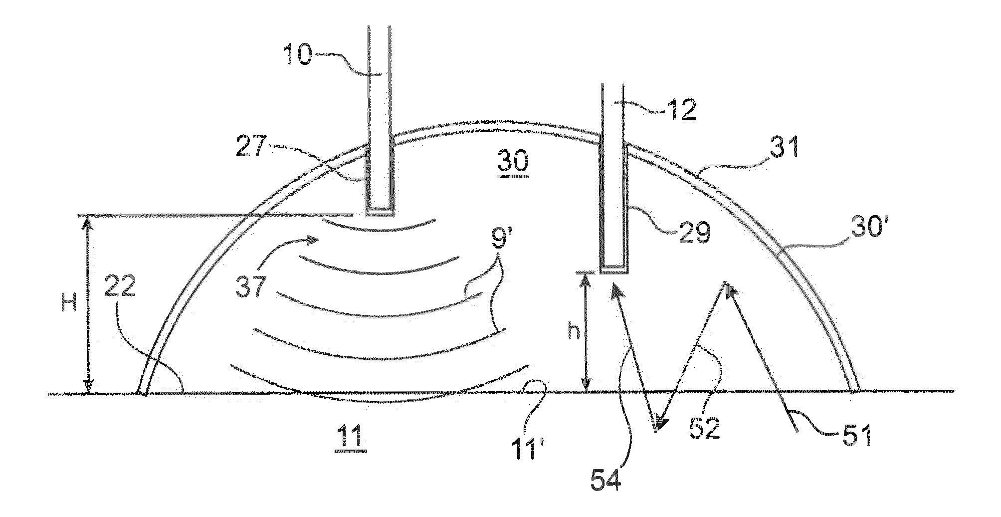
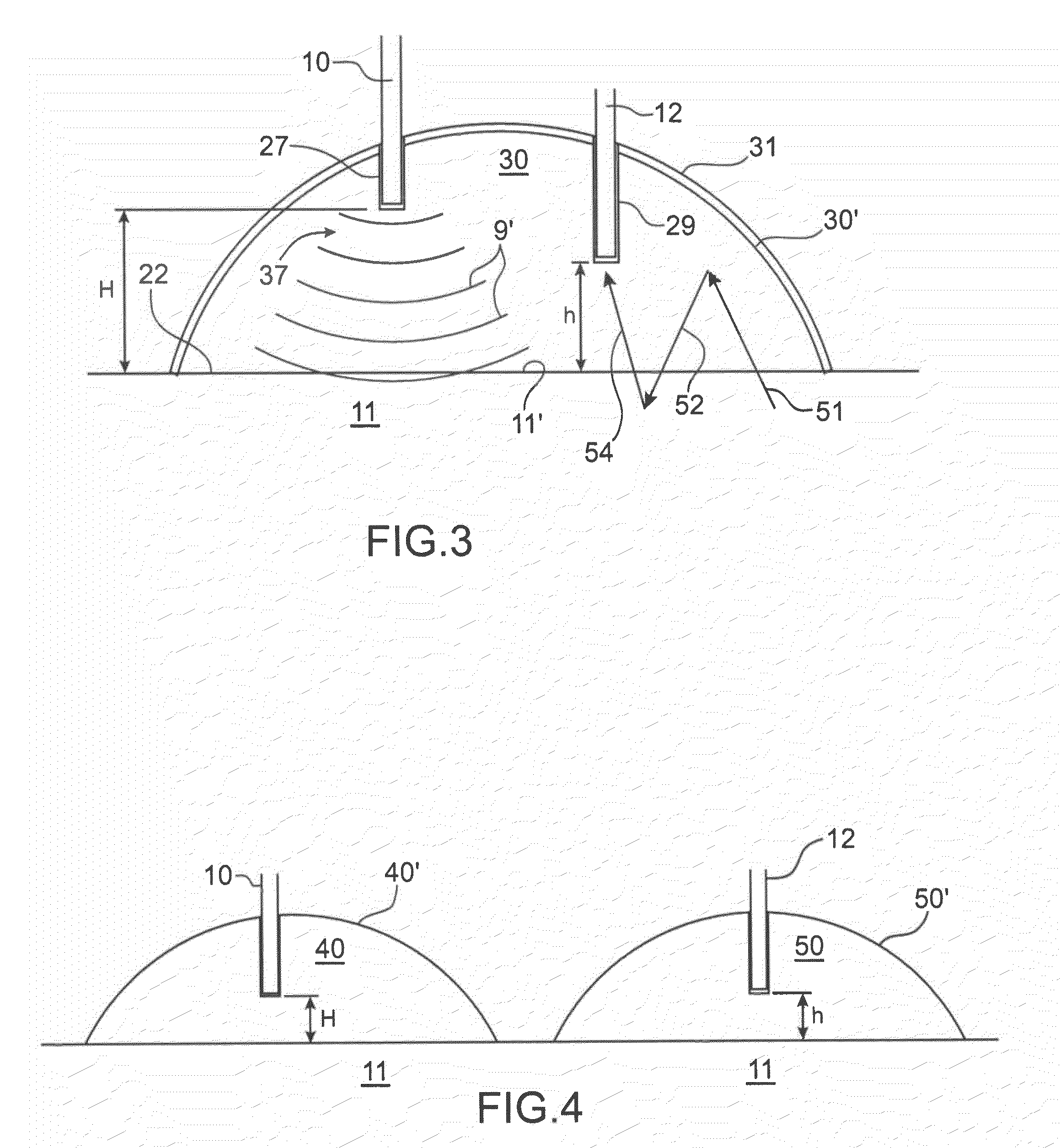
[0068]This figure illustrates the fibres 10, 12 which respectively bring an excitation beam 9 (or more generally an incident beam) into a diffusing medium to be examined 11, and collect a fluorescent or diffusion signal emanated by this same medium.

[0069]In this example, the ends of the two fibres 10, 12 are inserted in an interface element 20 in diffusing material. In the remainder hereof the expression > will be used, but either of the terms > or > may be used indifferently in its stead. This matrix may be in a solid material, but it can also be in a soft, viscous or liquid material, in which case it is intralipid for example.

[0070]The matrix here is of substantially cylindrical shape, having two faces 22, 24 perpendicular to the axis XX′ of revolution of the cylinder. One of these faces (face 24 in FIG. 2) comprises two openings 26, 28 for two cavities or housings 27, 29. These housings are intended to receiv...


PUM


Abstract

The invention concerns a coupling device for at least one optical fibre (10, 12) with a view to optical tomography-type examination of a medium (11) to be examined, comprising:
    • a mass (30) in diffusing material for a wavelength guided by the optical fibre, this mass comprising a bearing surface (22) to be applied against the surface (110) of the medium (11) to be examined,
    • at least one housing (27, 29) provided in the mass and capable of receiving the end of an optical fibre (10, 12).

Description

TECHNICAL FIELD AND PRIOR ART[0001]The invention concerns the field of diffuse optical imaging applied to the medical sphere and notably in vivo and ex vivo fluorescence imaging.[0002]These techniques can be used to implement non-invasive diagnosis systems through the use of non-ionizing radiation, which are easy to use and low cost.[0003]One application of diffuse optical imaging is fluorescence imaging, in which a fluorescent marker or fluorophore (chemical substance of a molecule capable of emitting fluorescent light after excitation) is injected into a subject to be examined and fixes itself to certain specific molecules e.g. cancerous tumours. The region of interest is illuminated at the optimal excitation wavelength of the fluorophore. A fluorescence signal is then detected.[0004]A diffuse optical imaging technique also exists without the injection of a fluorescent marker. In this case, it is sought to analyze a signal at the same wavelength as the excitation wavelength.[0005]...

Claims


Application Information

Patent Timeline
Patent Type & Authority Applications(United States)
IPC IPC(8): G06K9/00
CPCA61B5/0073A61B1/07G01N21/645A61B5/6843
Inventor GUYON, LAURENTBOUTET, JEROMEDEBOURDEAU, MATHIEU
Owner COMMISSARIAT A LENERGIE ATOMIQUE ET AUX ENERGIES ALTERNATIVES
Why Eureka
Try Eureka