
Swing bearing and method of processing raceway groove of the same

Inactive Publication Date: 2011-04-14
NTN CORP
View PDF5 Cites 16 Cited by
  • Summary
  • Abstract
  • Description
  • Claims
  • Application Information

AI Technical Summary

Benefits of technology

[0015]An object of the present invention is to provide the relative difference between the inter-raceway groove distances in a swing bearing assembly having double row raceway grooves, which difference can results in an increase of the bearing lifetime at such a cost that will not affect the productivity to the extent possible.
[0016]Another object of the present invention is to provide an inter-raceway groove processing method capable of accurately and efficiently processing the raceway grooves in the swing bearing assembly of a kind referred to above.
[0022]A forming or 
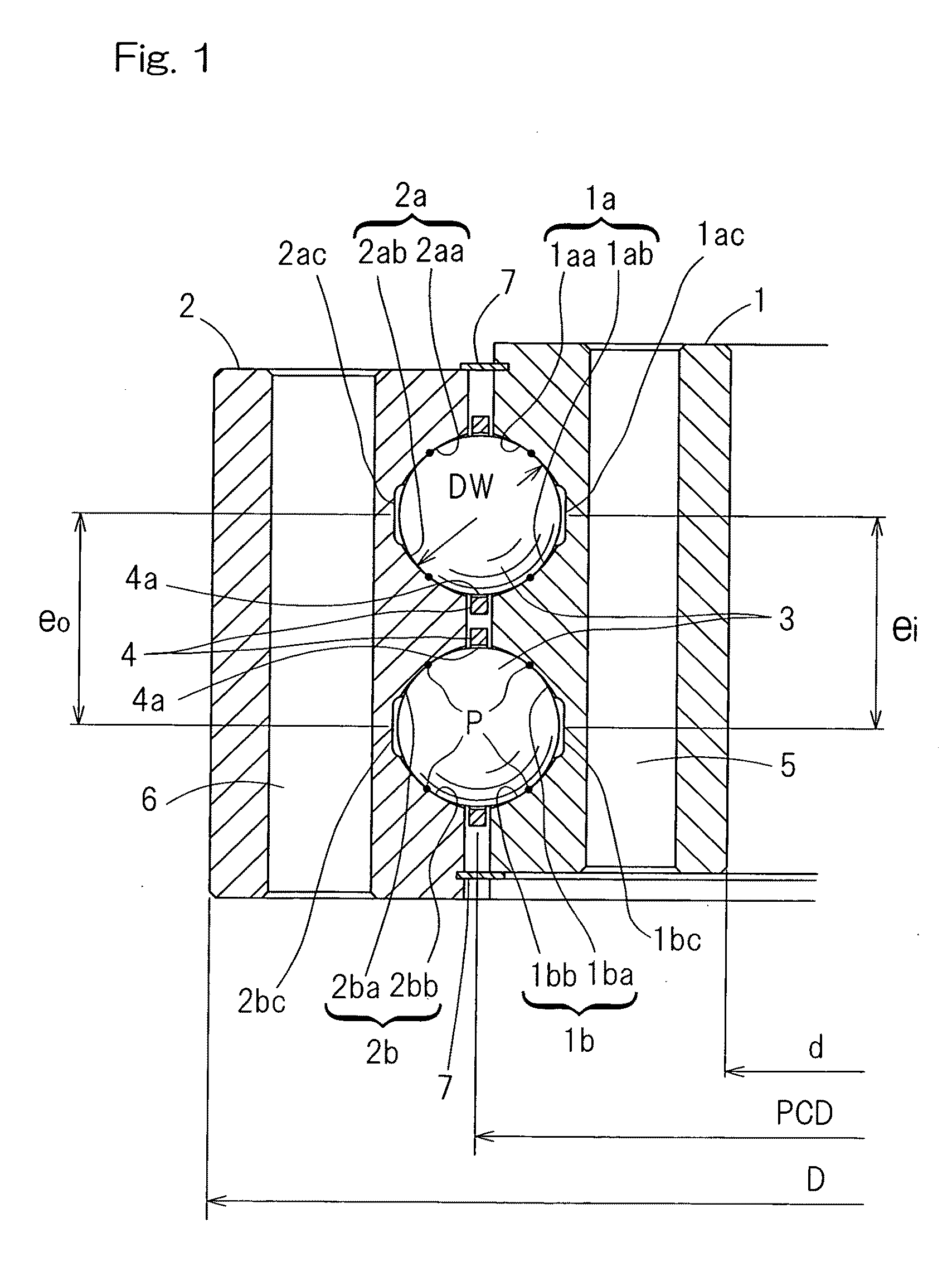
processing method for raceway grooves of a swing bearing assembly according to the present invention is such that the double row raceway grooves are formed in each of inner and outer rings, which is of one-piece structure, and a plurality of balls are interposed between the double row raceway grooves in the inner ring and the double row raceway grooves in the outer ring, respectively, and that the double row raceway grooves in the inner ring and the double row raceway grooves in the outer ring are simultaneously processed to reduce the difference between the distance from one row of the raceway groove in the inner ring to another row of the raceway groove in the inner ring and the distance from one row of the raceway groove in the outer ring to another row of the raceway groove in the outer ring to a value equal to or smaller than 50 μm.
[0024]If as suggested by the foregoing raceway groove processing method, the double row raceway grooves in the inner and outer rings are processed simultaneously, there is no possibility of occurrence of an error in mechanical accuracy and preciseness of the feeding for those double rows such as found in the case where those row raceway grooves in the inner and outer rings are processed separately in different process steps, and, hence, the preciseness of the inter-raceway groove distance is high. For this reason, the relative difference between the inter-raceway groove distances can be suppressed. In addition, simultaneous processing of the double rows of the raceway grooves results in a high processing efficiency. The swing bearing assembly having the raceway grooves, which have been processed by the raceway groove processing method of the present invention has a small relative difference between the inter-raceway groove distances and, therefore, the load can be uniformly imposed on the double row raceway grooves, thus making it possible to increase the lifetime.
[0026]The raceway grooves may be processed by the use of an alundum series grindstone. In this case, the shoulder height of the raceway grooves can be selected to such a sufficiently required value as to avoid a so-called shoulder run-on. Although as the shoulder height of the raceway grooves increases, points of contact of the grindstone shifts from an outer diametric portion, at which the peripheral velocity is high, to an end face at which the peripheral velocity is low, an undesirable excessive temperature rise during the processing of the raceway grooves can be avoided beforehand if the alundum series grindstones are used and other processing conditions are satisfied at the same time. The alundum series is soft as compared with the ceramic series. For this reason, scoring or scuffing can be avoided.
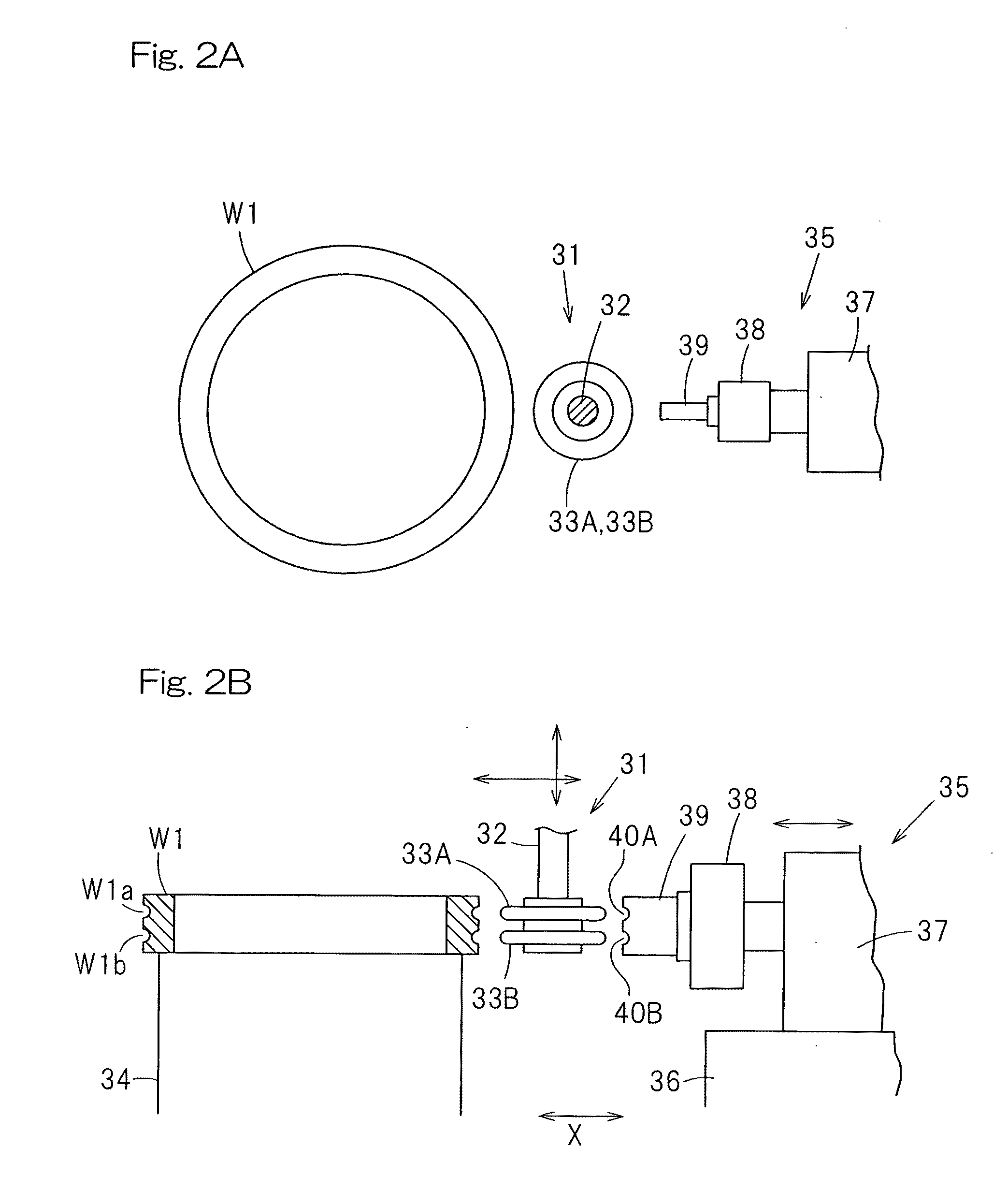
[0028]In order to shape the grindstone used for processing the raceway grooves a rotary dressing machine may be used and, at the same time, the amount of projection of diamond grains in this rotary dressing machine may be greater than 0.1 mm, smaller than 0.5 mm. In this case, the grindstone has an excellent grinding property to the raceway grooves, and when the raceway grooves are to be ground by such a grindstone, it is possible to shorten the length of time required to complete the grinding, as compared with that afforded when the amount of protrusion of the diamond grains is equal to or smaller than 0.1 mm.

Problems solved by technology

Each of those swing bearing assemblies used in the wind turbine is generally characteristically, inter alia, very large in size, relatively small in angle of pivot during the swing or in the yaw angle, and susceptible to a varying load.
That is to say, when an external load is imposed on the bearing assembly, the balance of loads acting on contact points P of the balls 3 with the inner and outer races 1 and 2 will become uneven to such an extent as to result in reduction in service life.
It can be suspected that if the relative difference Δe between the inter-raceway groove distances ei and eo (i.e., Δe=eo−ei) is large, the relative difference between the bearing gaps increases correspondingly, and, therefore, the unevenness in load balance increases.
In reality, however, to realize that the zero relative difference Δe is impossible and even an attempt to render the relative difference Δe to approach zero wherever possible is difficult to accomplish when considering the productivity and the cost.

Method used


Image

  • Swing bearing and method of processing raceway groove of the same
  • Swing bearing and method of processing raceway groove of the same
  • Swing bearing and method of processing raceway groove of the same

Examples


Embodiment Construction

[0047]A preferred embodiment of the present invention will now be described in detail with particular reference to FIG. 1. A swing bearing assembly shown therein is used as, for example, a bearing assembly for supporting a blade assembly of a wind turbine for angular movement about an axis substantially orthogonal to the longitudinal axis of a main shaft, or a bearing assembly for supporting a nacelle of the wind turbine on a support base for angular movement.

[0048]The swing bearing assembly referred to above includes an inner ring 1 having double row raceway grooves 1a and 1b defined therein, an outer ring 2 having double row raceway grooves 2a and 2b defined therein, double row balls 3 interposed between the raceway grooves 1a and 1b in the inner ring 1 and the raceway grooves 2a and 2b in the outer ring 2, and a ball retainer 4 for retaining each row of the balls 3 with those balls 3 accommodated within respective pockets 4a in the retainer 4. Each of the raceway grooves 1a, 1b, ...


PUM

PropertyMeasurementUnit
Lengthaaaaaaaaaa
Lengthaaaaaaaaaa
Lengthaaaaaaaaaa

Abstract

A swing bearing assembly includes a plurality of balls (3) interposed between double row raceway grooves (1a, 1b, 2a, 2b) in inner and outer rings (1, 2). The distance (ei) between the double row raceway grooves in the inner ring or the distance (eo) between the double row raceway grooves in the outer ring is within the range of a value equal to the diameter (Dw) of each of the balls to a value 1.7 times the diameter (Dw) and the diameter (Dw) of each of the balls is within the range of 30 to 80 mm, with the difference (Δe) between the raceway groove distance (ei) and the raceway groove distance (eo) chosen to be within the range of 5 to 50 μm. The double row raceway grooves are simultaneously processed with the use of alundum series grindstones.

Description

CROSS REFERENCE TO THE RELATED APPLICATION[0001]This application is based on and claims Convention priority to Japanese patent applications No. 2008-149124, filed Jun. 6, 2008, No. 2009-112561, filed May 7, 2009, and No. 2009-133628, filed Jun. 3, 2009, the entire disclosures of which are herein incorporated by reference as a part of this application.BACKGROUND OF THE INVENTION[0002]The present invention relates to a large-sized or supersized swing bearing assembly for use in a swivel mechanism employed for, for example, a blade assembly of a wind power generator and a method of forming a raceway groove employed in such bearing assembly.[0003]FIGS. 8 and 9 illustrate one example of a wind turbine utilizing a blade assembly for power generation by wind. The blade assembly 11 shown therein includes a nacelle 13 mounted on a support base 12 for angular movement in a horizontal plane, a horizontally extending main shaft 15 rotatably supported within a nacelle casing 14 forming a part of...

Claims


Application Information

Patent Timeline
IPC IPC(8): F16C33/58B23P17/00B24B1/00
CPCF03D11/0008F05B2260/74F16C19/181F16C33/64Y10T29/49689Y02E10/722Y02E10/726F16C2360/31F16C2300/14F03D80/70Y02E10/72F05B2240/50F16C33/58
Inventor HORI, MICHIOKUWAHARA, NURUMUYAMAMOTO, YOSHIFUMI
Owner NTN CORP
Learn More