
Multi-spindle machining machine

a machining machine and spindle technology, applied in the direction of attachment milling devices, metal-working machine components, manufacturing tools, etc., can solve the problems of increase production costs, and large size of machining machines, so as to achieve the effect of reducing size and production costs

Inactive Publication Date: 2011-04-14
SHENQ FANG YUAN TECH
View PDF14 Cites 21 Cited by
  • Summary
  • Abstract
  • Description
  • Claims
  • Application Information

AI Technical Summary

Benefits of technology

The primary object of the present invention is to provide a multi-spindle machining machine which can lower size and production cost.

Problems solved by technology

However, such a machining machine has a large size to increase production cost.
However, such a machining machine is in a large size to increase production cost.

Method used


Image

  • Multi-spindle machining machine
  • Multi-spindle machining machine
  • Multi-spindle machining machine

Examples


Embodiment Construction

The present invention will be clearer from the following description when viewed together with the accompanying drawings, which show, for purpose of illustrations only, the preferred embodiment in accordance with the present invention.

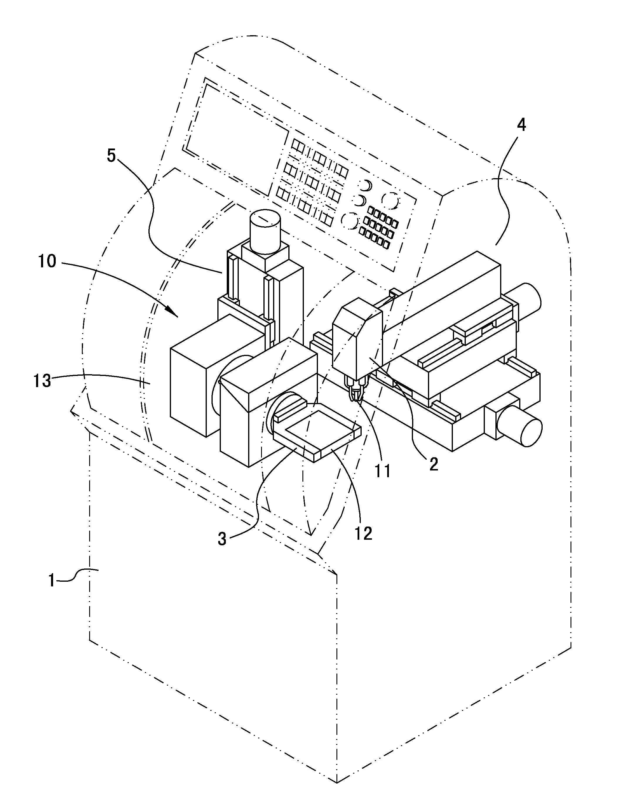
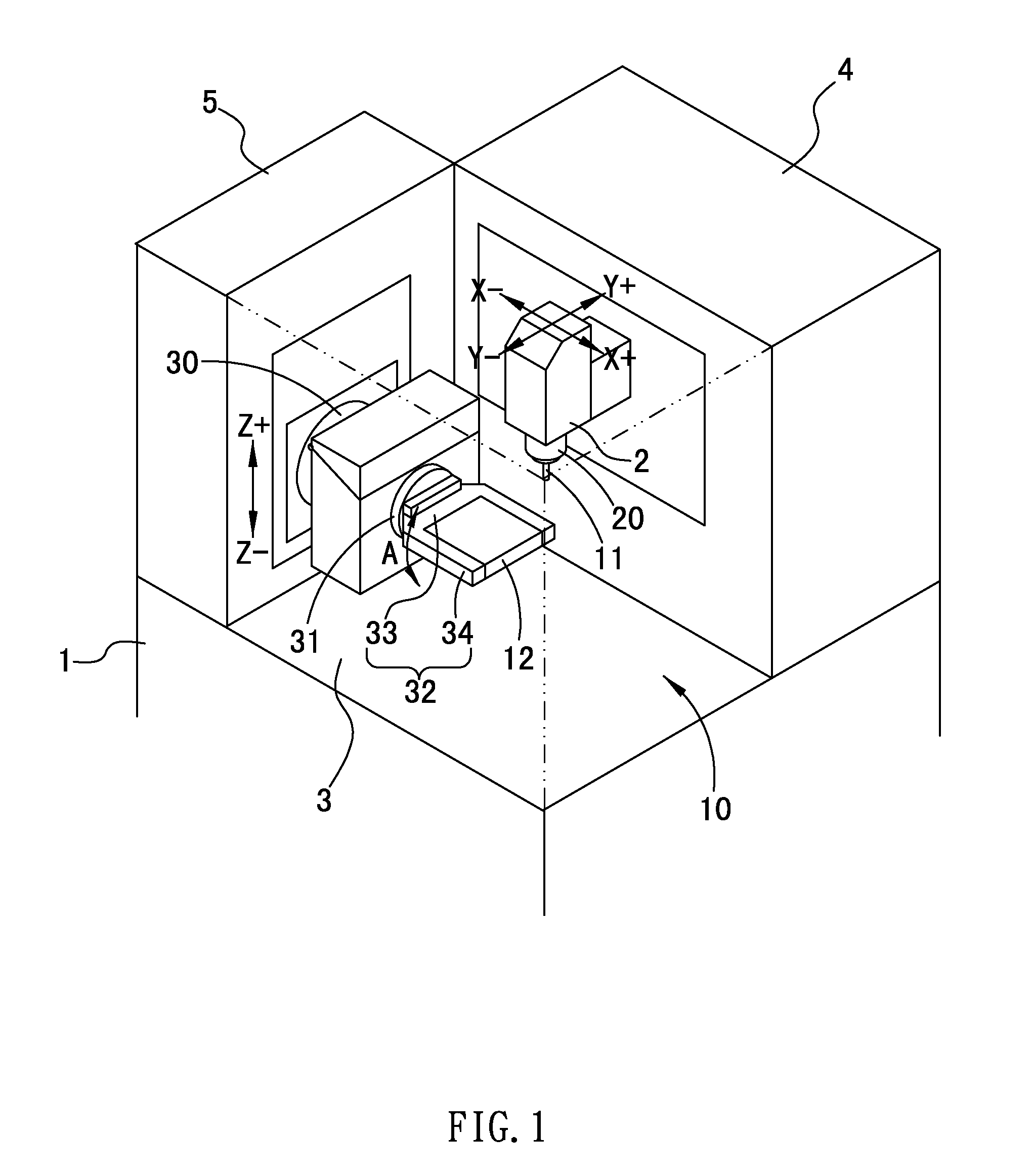
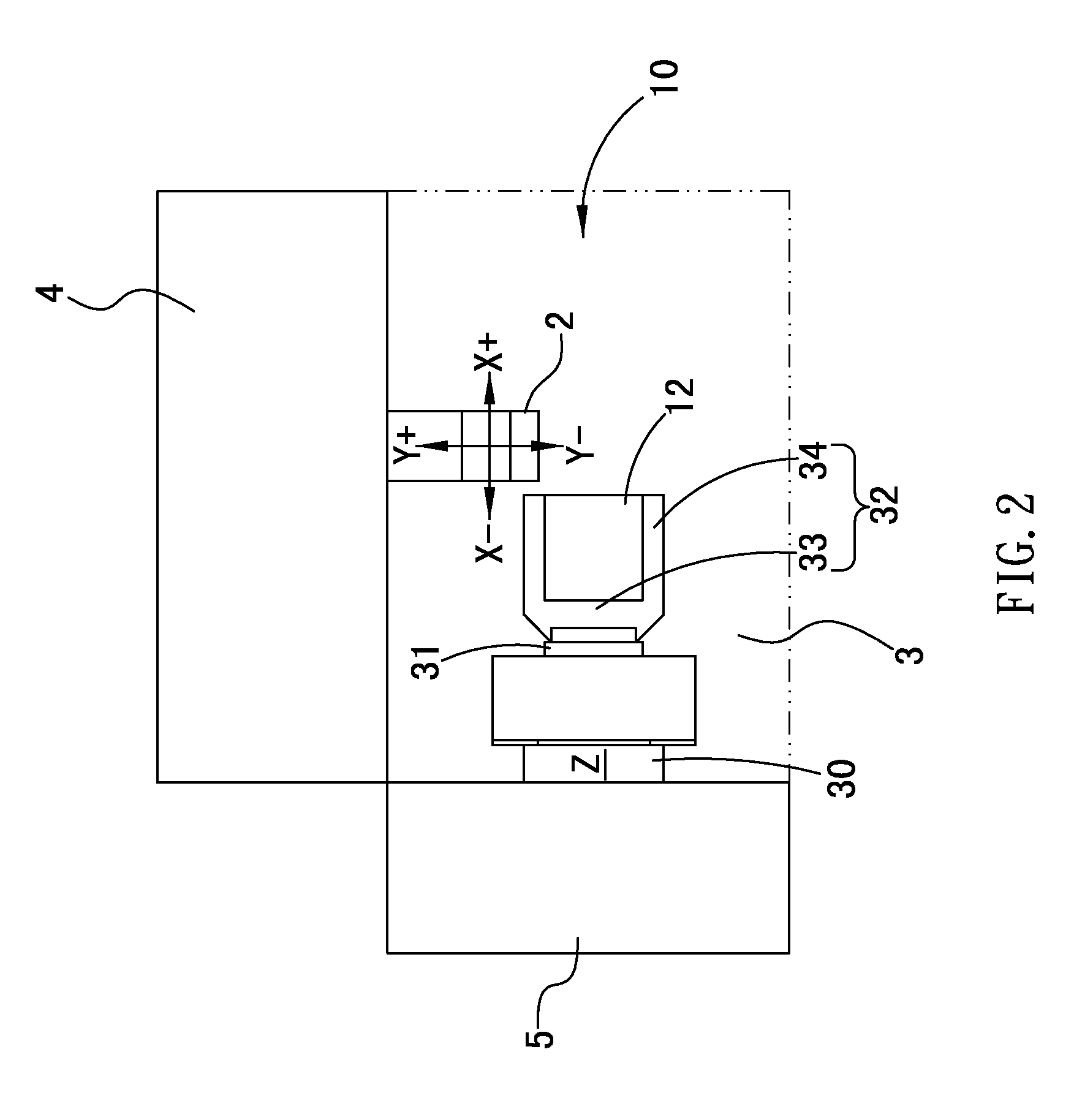
Referring to FIGS. 1-4, a multi-spindle machining machine in accordance with a preferred embodiment of the present invention comprises a base 1, a working head 2, a carrier 3, a lateral driving device 4, and a vertical driving device 5, wherein

the base 1 includes a working room 10 to move and rotate a tool 11 and a workpiece 12, the tool 11 is a milling cutter, a drill, and a grinding cutter, etc.

The working head 2 includes a driving spindle 20 to rotably disposed on a lower end thereof, and the lower end of the driving spindle 20 clamps the tool 11 to have a cutting, drilling, and grinding process.

The carrier 3 includes a seat 30, a rotary shaft 31, and a fixing holder 32. The seat 30 is fixed on one side of the working room 10. The rotary shaft 31 is...


PUM


Abstract

A multi-spindle machining machine comprises a base including a working room to move a tool and a workpiece; a working head including a driving spindle disposed on a lower end thereof to clamp the tool; a carrier including a seat fixed on one side of the working room, a rotary shaft mounted on the seat laterally to drive the seat to rotate in an axial direction, a fixing holder connected to the rotary shaft to fix the workpiece to the fixing holder; a lateral driving device disposed on the base and located on one side of the working room in a horizontal direction to drive the working head to move in X and Y axes; a vertical driving device disposed on the base and located on another side of the working room in a lateral direction to drive the seat to move in Z axis direction.

Description

BACKGROUND OF THE INVENTION1. Field of the InventionThe present invention relates to an automatic machining machine, and more particularly to a multi-spindle machining machine which can lower size and production cost.2. Description of the Prior ArtConventional lateral driving device of a machining machine is disposed on one side of a working room, and a vertical driving device is fixed on the lateral device so that a working head move along X axis by using the working head and along Y axis by using the vertical driving device. However, such a machining machine has a large size to increase production cost.Another conventional lateral device of a machining machine is fixed on a lower side of a working room, and a vertical driving device is mounted on an upper or lower sides so that the lateral driving device carries a workpiece on a carrier to move along X and Y axes, and the vertical driving device drives the carrier or a working head to move along a Z axis. However, such a machining...

Claims


Application Information

Patent Timeline
IPC IPC(8): B23B39/16B23C1/10
CPCB23Q1/4852B23Q11/0046B23Q11/0057Y10T409/30392Y10T29/5109Y10T409/309576Y10T409/309352Y10T29/5176Y10T408/38Y10T409/308792Y10T409/304032Y10T409/305656Y10T409/307504Y10T409/304088B23Q1/015
Inventor SHIH, CHENG HSIU
Owner SHENQ FANG YUAN TECH
Learn More