Condensate Pump

Active Publication Date: 2011-04-14
DIVERSITECH
View PDF31 Cites 27 Cited by
  • Summary
  • Abstract
  • Description
  • Claims
  • Application Information

AI Technical Summary

Benefits of technology

[0010]The presence of the low cost microcontroller as part of the water level sensor system results in numerous advantages. The motor control provided by the microcontroller is solid state thereby being completely silent and not subject to contact arcing, contact welding, or contact corrosion. The pump activation water levels are permanently stored in the memory of the microcontroller and are not subject to variation as may be the case with a mechanical float arm that bends or is otherwise damaged such as in shipment.
[0011]The presence of the low cost microcontroller as part of the water level sensor allows for additional features in the condensate pump that are not possible with mechanical floats and float switches. For example, the microcontroller can make and store precision time measurements, water level comparisons, pump and alarm output control parameters, and system metrics such as the number of pump starts. The microcontroller controls the operation of

Problems solved by technology

Condensate pumps are often located in extreme environments and subjected to moisture, heat, and cold.
Moreover, condensate pumps are often installed in inaccessible locations where maintenance is difficult, and therefore reliability over many years is necessary.
The condensate pump float is in contact with the

Method used


Image

  • Condensate Pump
  • Condensate Pump
  • Condensate Pump

Examples


Embodiment Construction

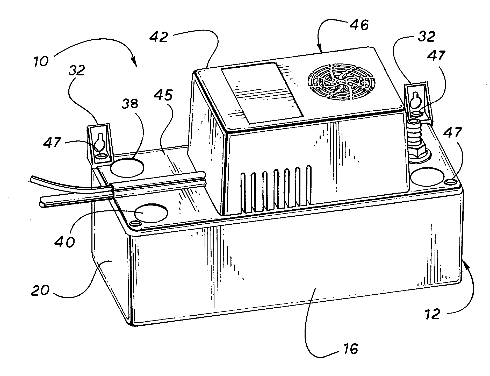
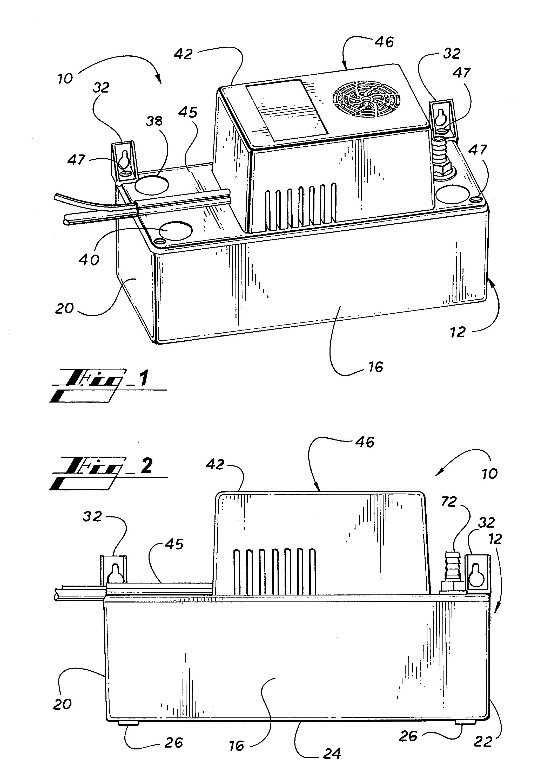
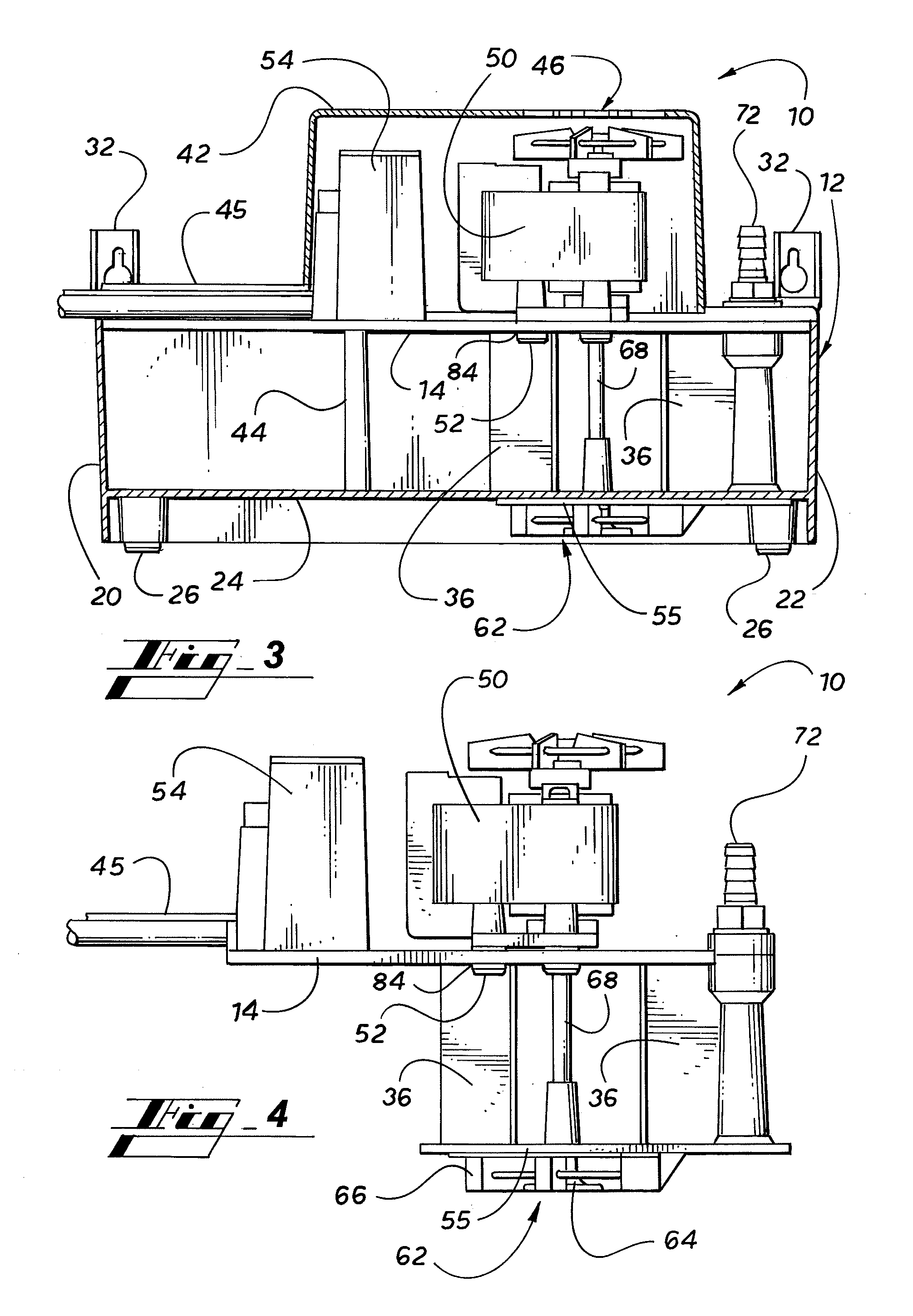
[0033]Turning to FIG. 1-7, a condensate pump 10 in accordance with the present invention comprises a reservoir 12, a top cover 46, and a support plate 14 (FIG. 4). The reservoir 12 comprises a water tight container with a front panel 16, a back panel 18, a left side panel 20, a right side panel 22, and a bottom panel 24. The reservoir may be of any geometric shape. The reservoir 12 has rubber support legs 26 located on the four corners of the bottom panel 24.

[0034]The top cover 46 comprises a cowl 42 and a flat base 45. The flat base 45 of the cover 46 is attached to the top of the reservoir 12 by means of cover screws 47. In addition, hanger brackets 32 are mounted to the reservoir 12 by means of the cover screws 47 adjacent the reservoir back panel 18. The hanger brackets 32 are used to mount the condensate pump 10 on a wall or other elevated support in order to make later access to the condensate pump 10 in some cases easier. The cowl 42 covers and protects pump motor 50 and cont...


PUM


Abstract

A condensate pump for an HVAC system includes a reservoir for collecting condensate water, a pump motor connected to an impeller pump for pumping the condensate water out of the reservoir, and a floatless pump controller. The floatless pump controller detects the water level in the reservoir and, based on the water level in the reservoir, controls the operation of the pump motor, and if necessary, sounds an alarm and shuts down the HVAC system. The floatless pump controller may employ an ultrasonic transducer or capacitance sensors to detect the level of condensate water in the reservoir.

Description

CLAIM OF PRIORITY[0001]This application is a continuation-in-part of copending U.S. patent application Ser. No. 11 / 277,445, filed Mar. 24, 2006, which claims priority from U.S. Provisional Patent Application Ser. No. 60 / 665,533, filed on Mar. 24, 2005, this application is a continuation-in-part of copending U.S. patent application Ser. No. 12 / 190,212, filed Aug. 12, 2008, which claims priority from U.S. Provisional Patent Application Ser. No. 60 / 956,741, filed on Aug. 20, 2007, and this application claims priority from U.S. Provisional Patent Application Ser. No. 60 / 976,962, filed on Oct. 2, 2007, which is incorporated herein in its entirety.FIELD OF THE INVENTION[0002]The invention relates to a condensate pump that collects condensate water from the evaporator of an HVAC system and pumps the condensate water to another location for disposal. More specifically, the condensate pump of the present invention includes a floatless water level sensing device.BACKGROUND OF THE INVENTION[00...

Claims


Application Information

Patent Timeline
IPC IPC(8): F04B49/06
CPCF04D13/16F24F13/222F04D15/0218
Inventor WARD, CHARLES BARRY
Owner DIVERSITECH
Why Eureka
Try Eureka