Magnetization of non-magnetized permanent magnet segments in electical machines

a technology of electical machines and permanent magnets, which is applied in the field of electric machines, can solve the problems of cumbersome process of assembling the rotor from pre-magnetized permanent magnet segments and easy physical accidents of the process

Active Publication Date: 2011-04-21
NUOVO PIGNONE TECH SRL
View PDF6 Cites 6 Cited by
  • Summary
  • Abstract
  • Description
  • Claims
  • Application Information

AI Technical Summary

Benefits of technology

[0005]In accordance with an embodiment of the invention, a method for magnetizing a rotor of an electrical machine is provided. The method includes assembling an array of non-magnetized anisotropic permanent magnet segments around a rotor spindle encased in a retaining ring. The method also includes determining multiple optimal magnetization orientation directions of the non-magnetized anisotropic permanent magnet segments. Further, the method includes positioning the assembled non-magnetized anisotropic permanent magnet segments around the rotor spindle such that the optimal magnetization orientation directions of the anisotropic permanent magnet segments are aligned with multiple flux lines produced by a magnetization fixture. Finally, the method includes energizing the magnetization fixture for magnetizing the segments via a pulse direct current for an optimal duration of the pulse.
[0006]In accordance with another embodiment of the invention, a magnetizer system for a rotor of an electrical machine is provided. The magnetizer system includes a magnetizing yoke, wherein the magnetizing yoke comprises multiple pole-pieces extending therefrom. The magnetizer system also includes multiple coils wound around the pole-pieces. Further, the magnetizer system includes a magnetizing circuit for energizing a magnetization fixture via a pulse direct current for an optimal duration of the pulse.

Problems solved by technology

However, assembly of the rotor from pre-magnetized permanent magnet segments may be a cumbersome process, especially in larger electrical machines, as it may be time consuming and unwieldly.
The process is prone to physical accidents if energized permanent magnet blocks escape restraint.

Method used


Image

  • Magnetization of non-magnetized permanent magnet segments in electical machines
  • Magnetization of non-magnetized permanent magnet segments in electical machines
  • Magnetization of non-magnetized permanent magnet segments in electical machines

Examples


Embodiment Construction

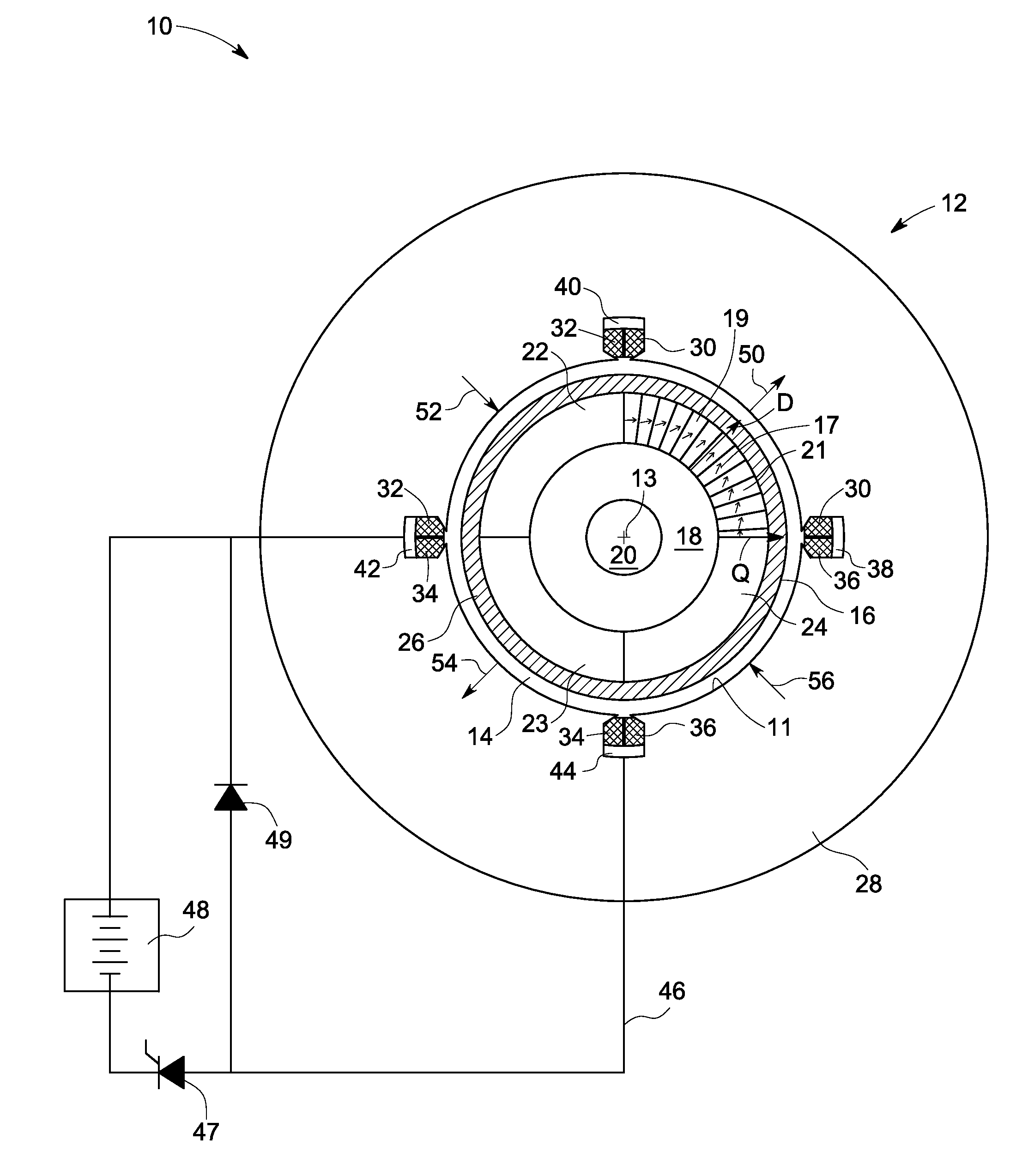
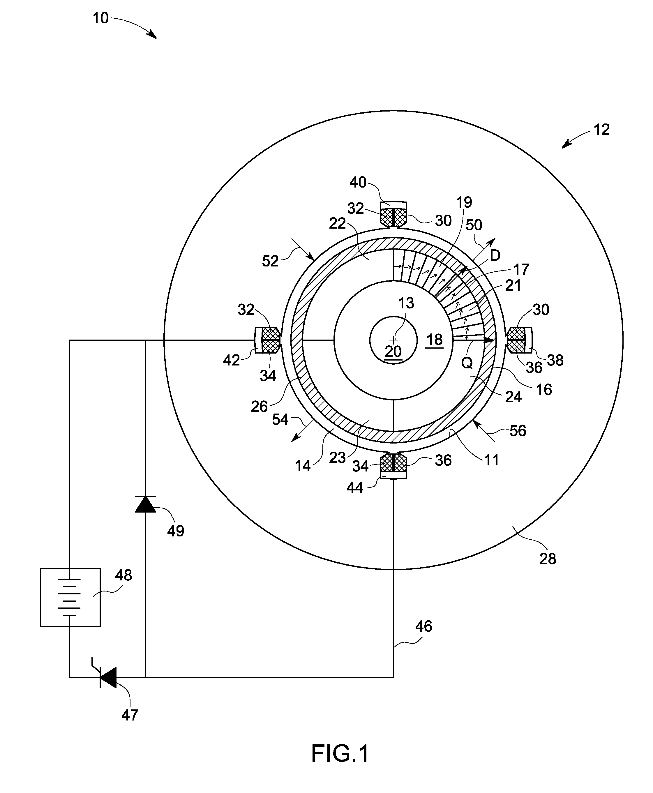
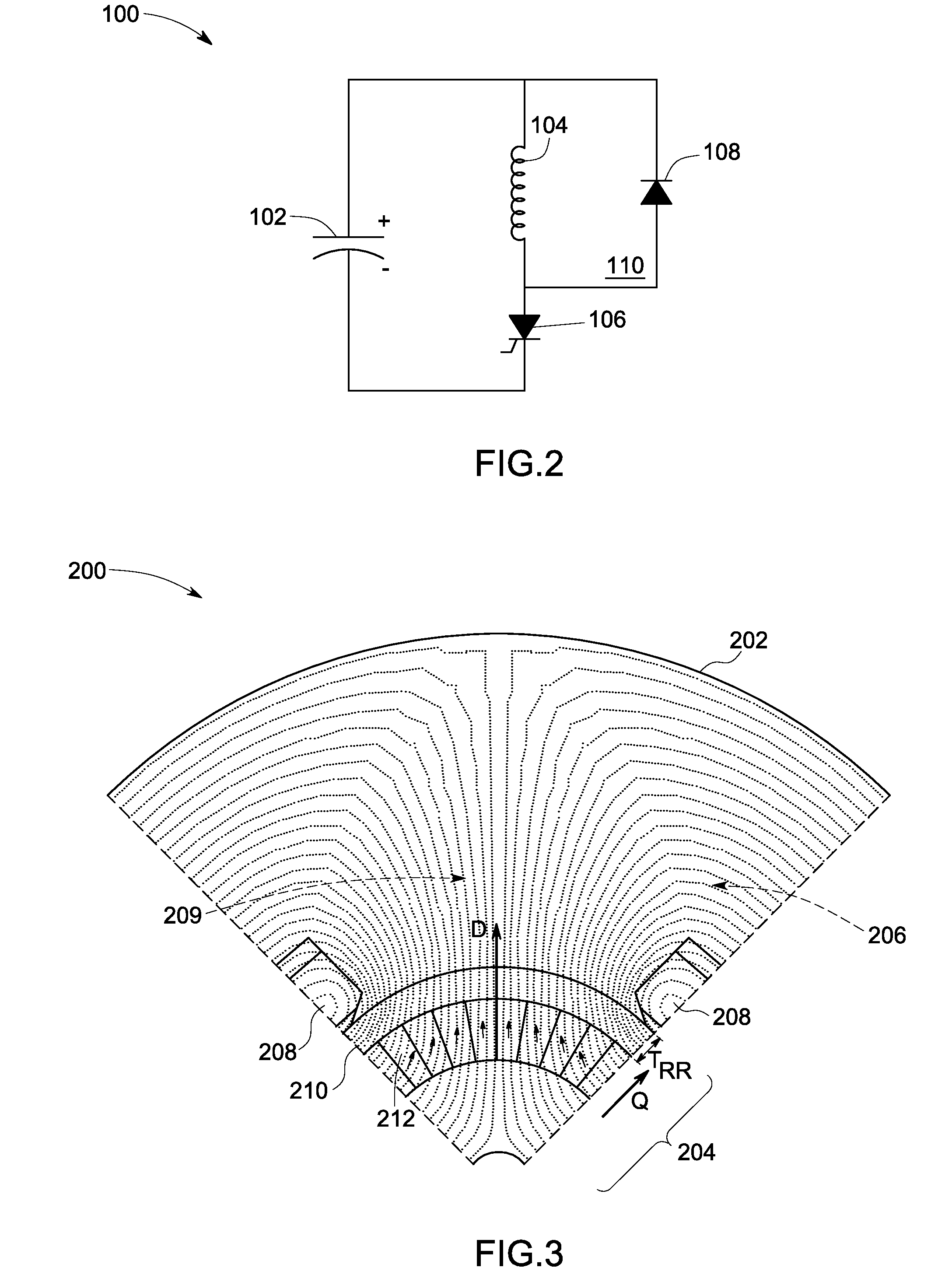
[0015]As discussed in detail below, embodiments of the invention are directed towards magnetizing of a rotor of an electrical machine using a pulse direct current for an optimal duration of the pulse. As used herein, the term ‘crowbar’ refers to an electrical circuit used to prevent an overvoltage condition of a power supply unit from damaging the circuits attached to the power supply. The present invention addresses methods of assembling a rotor including non-magnetized permanent magnet segments with metallic retaining ring and magnetizing the rotor in a magnetizer system that includes flowing of current for an optimal duration in the pulse. The present invention is also directed towards the calculation of the optimal “on time” of the switch controlling the current flow, which is requisite for effectively magnetizing the non-magnetized permanent magnet segments of the rotor by suppressing the eddy currents in the retaining ring of the rotor.

[0016]When introducing elements of variou...


PUM

PropertyMeasurementUnit
anisotropicaaaaaaaaaa
magnetizationaaaaaaaaaa
timeaaaaaaaaaa

Abstract

A method for magnetizing a rotor of an electrical machine is provided. The method includes assembling an array of non-magnetized anisotropic permanent magnet segments around a rotor spindle encased in a metallic ring. The method also includes determining multiple optimal magnetization orientation directions of the non-magnetized anisotropic permanent magnet segments. Further, the method includes positioning the assembled non-magnetized anisotropic permanent magnet segments around the rotor spindle such that the optimal magnetization orientation directions of the anisotropic permanent magnet segments are aligned with multiple flux lines produced by a magnetization fixture. Finally, the method includes energizing the magnetization fixture for magnetizing the segments via a pulse direct current for an optimal duration of the pulse.

Description

BACKGROUND[0001]The invention relates generally to electrical machines and more particularly, to magnetization of permanent magnet rotors in electrical machines.[0002]Generally, an electrical machine, such as a motor or a generator, includes a rotor disposed within a stator and utilized to convert electrical power to mechanical power or vice versa. Certain electrical machines use permanent magnet type rotors, which rotors reduce the size and enhance the overall efficiency of the machine. Such a rotor generally includes an annular permanent magnet, disposed over a rotor spindle. In larger machines, the permanent magnet is generally formed by assembling a plurality of permanent magnets assembled around a rotor spindle. In general, the permanent magnet segments are magnetized prior to assembly on the rotor spindle. For example, the permanent magnet segments are cut and ground to shape from larger unfinished magnet blocks, after which the segments are magnetized individually in a soleno...

Claims


Application Information

Patent Timeline
Patent Type & Authority Applications(United States)
IPC IPC(8): H02K15/03H01F13/00
CPCH02K1/278Y10T29/49012Y10T29/49009H02K15/03H01F13/003
Inventor STEPHENS, CHARLES MICHAELWEEBER, KONRAD ROMANGALIOTO, STEVEN JOSEPHCARL, JR., RALPH JAMES
Owner NUOVO PIGNONE TECH SRL
Why Eureka
Try Eureka