Structure and method for the collection of an evaporated fluid

a technology of structure and method, applied in the direction of water/sludge/sewage treatment, lighting and heating apparatus, applications, etc., can solve the problems of reduced arable land, glacier melting faster than usual, and wide flooding

Inactive Publication Date: 2011-04-21
IEARDI JOSEPH
View PDF9 Cites 8 Cited by
  • Summary
  • Abstract
  • Description
  • Claims
  • Application Information

AI Technical Summary

Benefits of technology

[0011]In an embodiment, a spacer may be included to inhibit significant movement of the arcuate trough when the tensioning apparatus is tensioned, and a portion of the edge may be encouraged to abut the tensionable covering to facilitate transmission of condensate from the covering into the collector.
[0014]In an embodiment, the structure may include at least one fan for encouraging formation of the condensate upon the covering.

Problems solved by technology

For example, glaciers may be melting faster than desired with the possibility of world wide flooding in some coastal areas.
Additionally, there may be water shortages for drinking and agricultural irrigation, and deforestation which may cause less carbon dioxide to be absorbed by vegetation.
Further, a reduction in arable land may compound difficulties in food production.
Similarly, overgrazing of existing land may in turn expands the desert area world wide.
Existing systems of treatment of water have tended to be expensive when large amounts of water are to be treated or collected.
Difficulty has also been found in collecting any fluid that has been evaporated in an attempt to purify it.
Other systems that have been built may lack portability and / or the ability to locate such systems in unforgiving environments, such as in a desert.

Method used


Image

  • Structure and method for the collection of an evaporated fluid
  • Structure and method for the collection of an evaporated fluid
  • Structure and method for the collection of an evaporated fluid

Examples


Embodiment Construction

[0039]Similar references are used in different figures to denote similar components.

[0040]The disclosed structure may use energy, for example of the sun, to resolve the problem of the need for usable water by taking advantage of what occurs in nature to incur a limited or no detrimental effect to the environment.

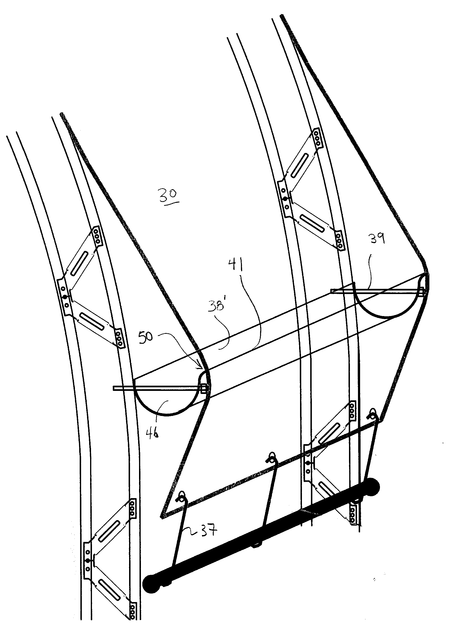
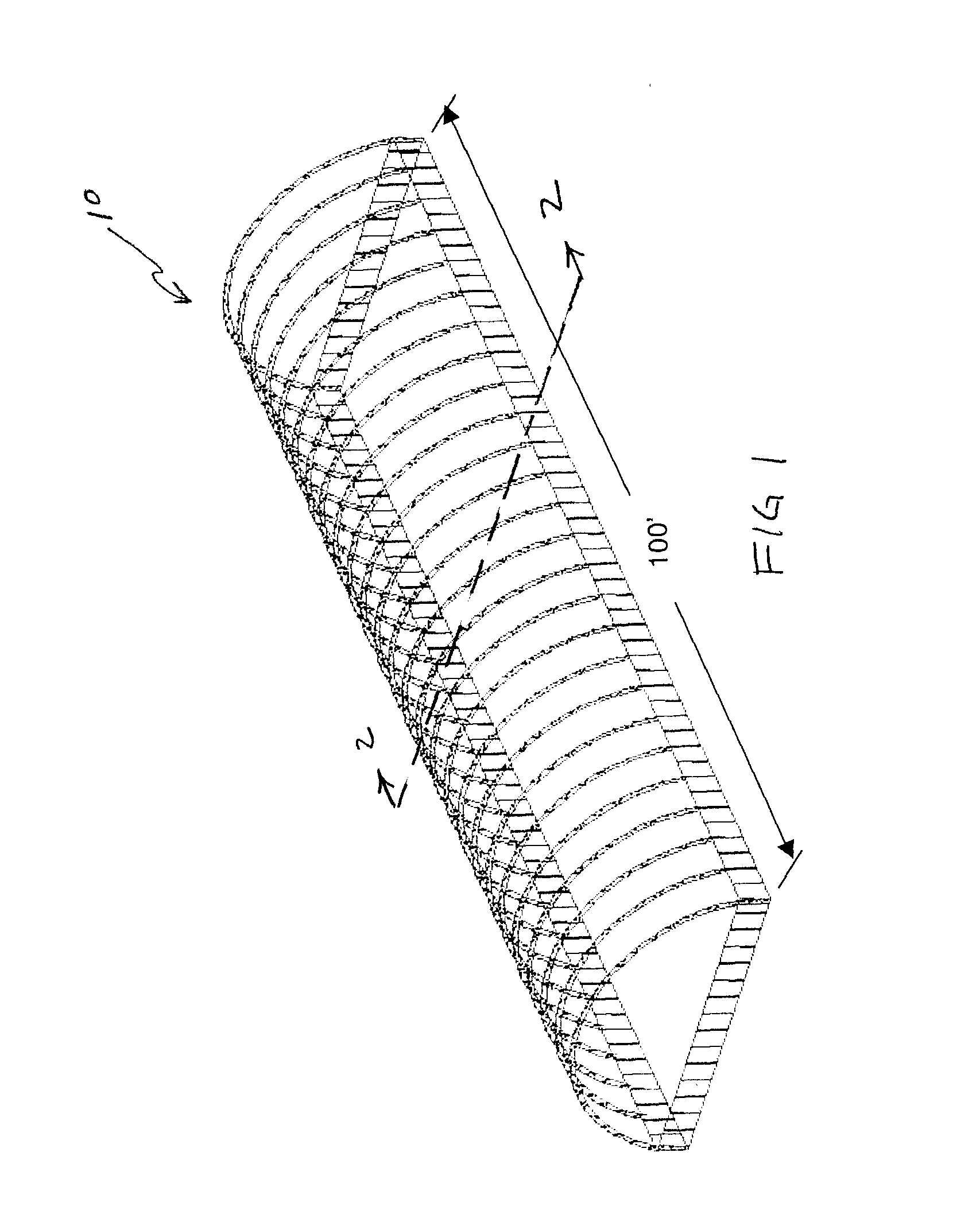
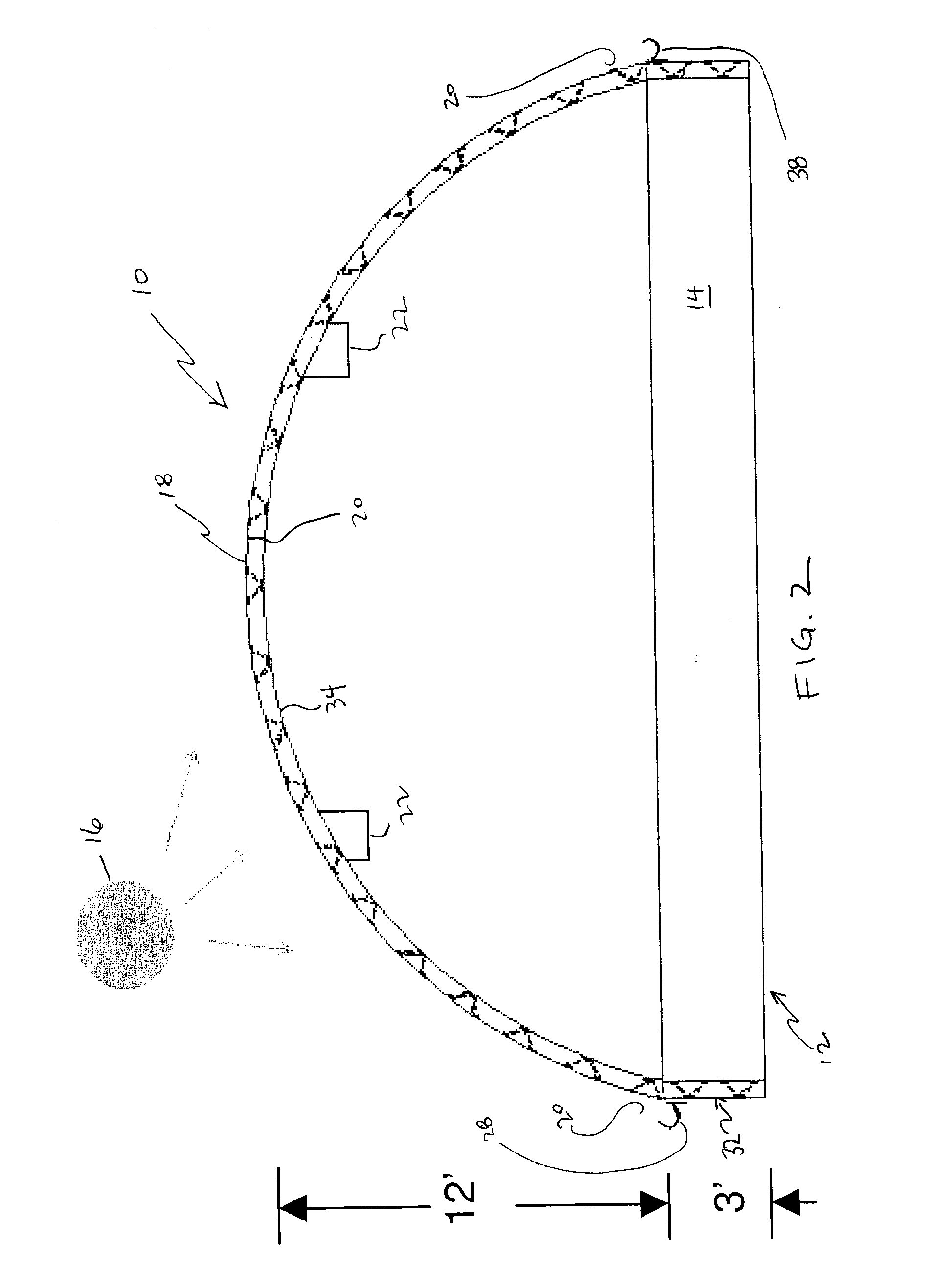
[0041]The present structure may be employed in a hot desert with proximity to salt or unusable water, and convert desert or poor land, to farm and / or forest land. Water collected through condensation may be captured by the structure canopy, and can be used to irrigate as well as produce potable water.

[0042]The structure may be positioned at an edge of a desert near a water source, and slowly recapture the desert land by converting unusable or poor water to usable water. Based on the vegetation chosen, once sustainable growth is achieved, the structure may be relocated to the next area for treatment.

[0043]For example, at a constant average temperature of 95 to 105 degrees Fah...


PUM

PropertyMeasurementUnit
temperatureaaaaaaaaaa
depthaaaaaaaaaa
structureaaaaaaaaaa

Abstract

A structure for the collection of an evaporated fluid is disclosed. The structure may include a reservoir for holding a liquid. The reservoir may have an open end, and an enclosure mounted about the open end of the reservoir for entrapping a fluid evaporated from the reservoir. The enclosure may include a support structure, and a tensionable covering supported by the support structure. The structure also may include a collector for collecting condensate from the covering, the collector being mounted to the support structure, intermediate the support structure and the covering, and oriented to receive condensate moved by gravity along the covering. A tensioning apparatus may be employed for tensioning the covering about the collector to encourage the condensate to engage the collector. The condensate may then be transported within the collector to a desired location.

Description

FIELD OF THE INVENTION[0001]The invention relates to a structure and method for the collection of an evaporated fluid, and is concerned with treating fluids, for example by distillation, to make them potable or usable for the production of foodstuffs.BACKGROUND OF THE INVENTION[0002]There may be an over abundance of carbon dioxide in some or all of the planet. For example, glaciers may be melting faster than desired with the possibility of world wide flooding in some coastal areas. Additionally, there may be water shortages for drinking and agricultural irrigation, and deforestation which may cause less carbon dioxide to be absorbed by vegetation. Further, a reduction in arable land may compound difficulties in food production. Similarly, overgrazing of existing land may in turn expands the desert area world wide.[0003]Fluids, in particular water, have been processed and cleaned through a variety of known processes. For example, water has been purified or desalinated by the use of d...

Claims


Application Information

Patent Timeline
Patent Type & Authority Applications(United States)
IPC IPC(8): F25D21/14
CPCB01D1/0035B01D5/0066E04B1/3205C02F1/14E03B3/28B01D5/009Y02A20/00Y02A20/212
Inventor IEARDI, JOSEPH
Owner IEARDI JOSEPH
Why Eureka
Try Eureka