
Solar Energy Converter and Method for Converting Solar Energy

a solar energy converter and solar energy technology, applied in the direction of heat collector mounting/support, thermal-pv hybrid energy generation, lighting and heating apparatus, etc., can solve the problems of complicated tubes/pipes, failure to provide a fast and efficient way to assemble the entire system, and circulating water in the panel may freeze and burst pipes

Active Publication Date: 2011-04-21
SOLEEVA CORP
View PDF11 Cites 32 Cited by
  • Summary
  • Abstract
  • Description
  • Claims
  • Application Information

AI Technical Summary

Benefits of technology

[0008]A purpose of the present invention is to provide a simple, reliable and inexpensive solar energy converter without complicated tubes / pipes for generating electric energy and heated fluid.
[0012]A purpose of the present invention is to provide a simple, reliable and inexpensive solar energy conversion system without complicated tubes / pipes for generating electric energy and heated fluid.
[0016]Accordingly, the solar energy converter of the present invention eliminates the need to utilize assembled piping, such as copper piping, internally under the photovoltaic panel. The multi-layer assembly and the manifold assembly can be manufactured in one step respectively, and the solar energy conversion system provides a user to easily assemble multiple units of the system by mounting them on the frame to accommodate the user's needs.

Problems solved by technology

However, the system employs the tubes / pipes which are complicated to fabricate and failed to provide a fast and efficient way to assemble the entire system.
Besides, the system also suffers from cold and icy conditions, where the temperature is such that circulating water in the panel may freeze and burst the pipes.
Thus, the complicated tubes / pipes shall be a problem for maintaining such system.

Method used


Image

  • Solar Energy Converter and Method for Converting Solar Energy
  • Solar Energy Converter and Method for Converting Solar Energy
  • Solar Energy Converter and Method for Converting Solar Energy

Examples


Embodiment Construction

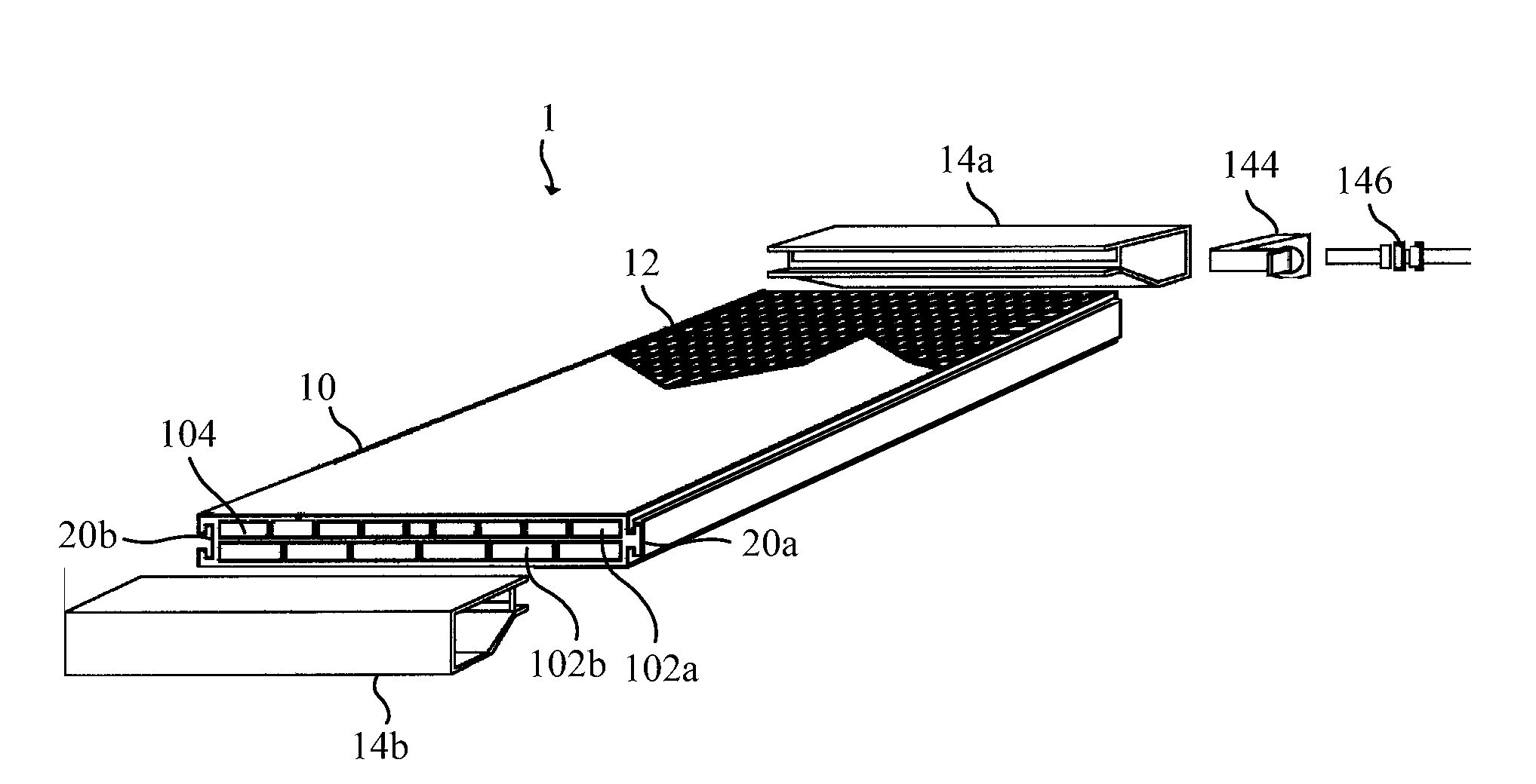
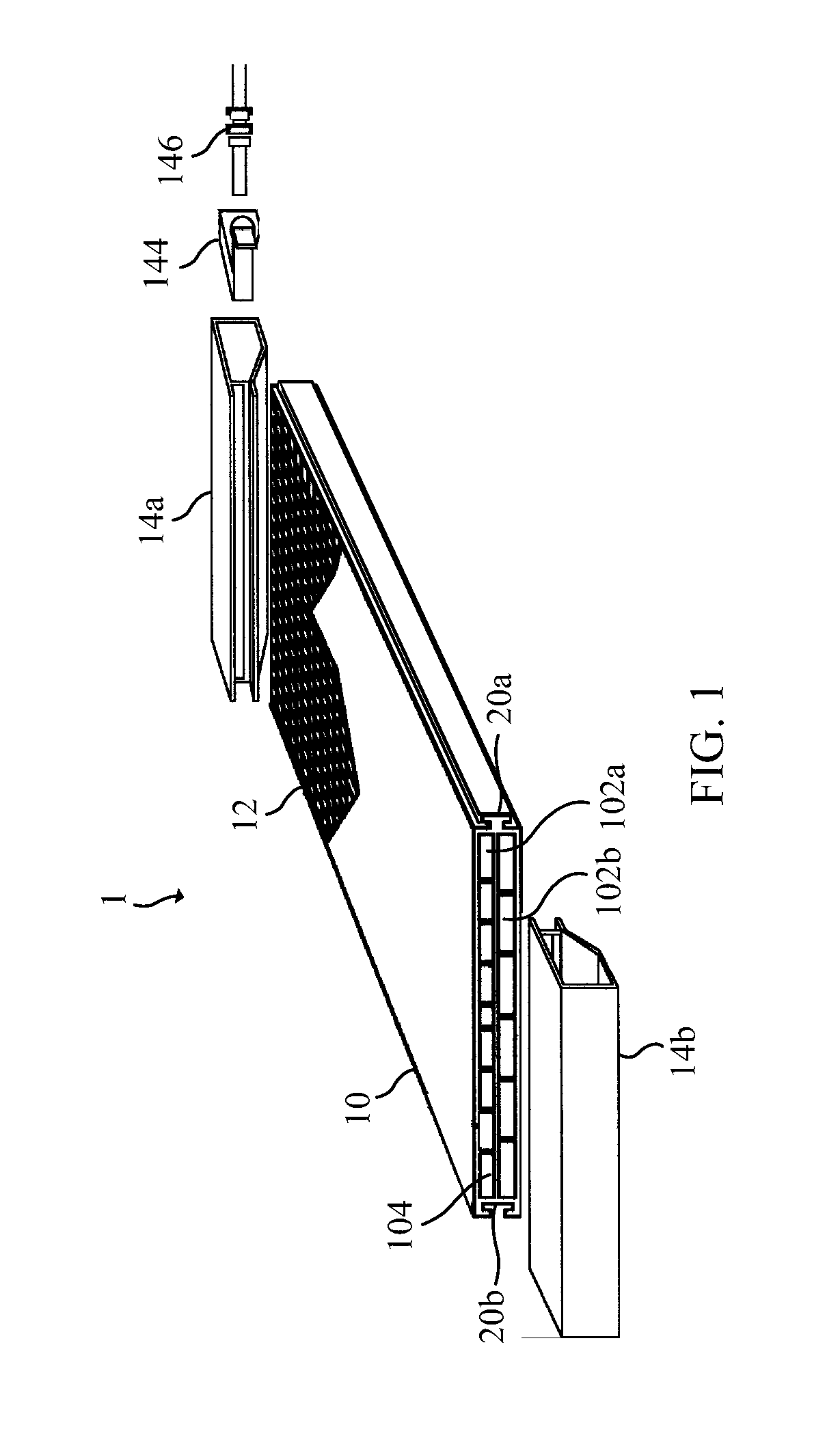
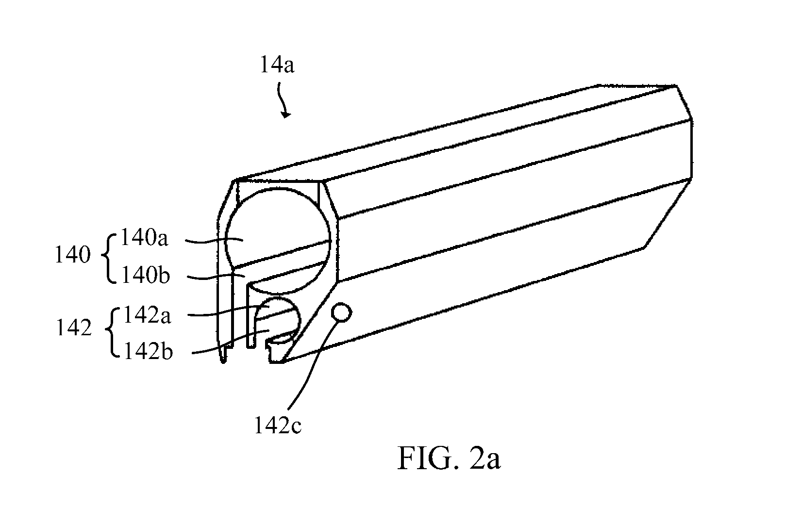
[0034]Please refer to FIG. 1, FIG. 1 illustrates a 3D diagram of a solar energy converter according to an embodiment of the invention. As shown in FIG. 1, the solar energy converter 1 has a multi-layer assembly 10, a photovoltaic panel 12, a manifold assembly comprising a first manifold unit 14a and a second manifold unit 14b.

[0035]The multi-layer assembly 10 is a casing and comprises N layers separated by a plurality of separator floors, N is a positive integer. For example, the multi-layer assembly 10 has two layers, first layer 102a and second layer 102b, in this embodiment, and the two layers are separated by a separator floor 104. In practice, each of the N layers of the multi-layer assembly 10 shall be parallel to one another, and each layer has several channels adapted to contain a fluid stream. For example, the first layer 102a may be adapted to contain water stream and the second layer 102b may be adapted to contain air stream. The channels of all the layers form a pattern...


PUM


Abstract

The solar energy converter for generating electric energy and heated fluid comprises a multi-layer assembly, a photovoltaic panel and a manifold assembly. The multi-layer assembly is a casing and comprises N layers separated by at least one separator floor, each layer has at least one channel adapted to contain a fluid stream, and each layer has a first opening and a second opening. The photovoltaic panel has a top surface and a bottom surface, the bottom surface of the photovoltaic panel contacts the multi-layer assembly. The manifold assembly comprises N passages for containing the fluid streams, the Kth passage is adapted to distribute the fluid stream to be heated into the channel of the Kth layer through the corresponding first opening and collect the heated fluid stream from the channel of the Kth layer through the corresponding second opening, wherein N is a positive integer, K is a positive integer less than or equal to N.

Description

[0001]This application is a utility patent application that claims priority to co-pending U.S. Provisional Patent Application having Ser. No. 61 / 252,635, filed Oct. 16, 2009, which is entirely incorporated herein by reference.BACKGROUND OF THE INVENTION[0002]1. Field of the Invention[0003]The invention is related to a solar energy converter. More particularly, the invention is related to the solar energy converter for generating electric energy and heated fluid.[0004]2. Description of the Prior Art[0005]In general, traditional solar panels may have photovoltaic arrays placed on a flat plate for converting solar energy to electric energy, a series of tubes are secured to the flat plate for collecting solar radiation onto to the flat plate and the photovoltaic arrays, and water to be heated is circulated through these tubes to extract the heat received by the photovoltaic arrays and the flat plate. Furthermore, the water circulated through these tubes may be used as a coolant for taki...

Claims


Application Information

Patent Timeline
IPC IPC(8): H01L31/052F24J2/24F24S10/50F24S10/70
CPCF24J2/0477F24J2/202F24J2/4647F24J2002/0092F24J2002/467H01L31/058Y02E10/50Y02E10/60H02S20/00H02S40/44H01L31/0422Y02E10/44F24S10/20F24S10/502F24S80/30F24S2020/17F24S2025/6007H01L31/042H01L31/052
Inventor AHLGREN, RALPH B.PETRY, KLAUSFLORES, A. MICHAEL
Owner SOLEEVA CORP
Learn More