Optical Array Device and Methods of Use Thereof for Screening, Analysis and Manipulation of Particles

a technology of optical arrays and filters, applied in the direction of optical radiation measurement, luminescent dosimeters, instruments, etc., can solve the problems of time-consuming and laborious to isolate a sufficient number of cells, and the current optical array techniques and methodologies are not readily extended to create multiple beams, etc., to achieve simple, straightforward, and easy to address

Active Publication Date: 2011-04-21
TUFTS UNIV
View PDF20 Cites 39 Cited by
  • Summary
  • Abstract
  • Description
  • Claims
  • Application Information

AI Technical Summary

Benefits of technology

[0014]In one embodiment of the invention, laser light is coupled into the optical array to create an array of optical traps, or tweezers, providing a simple, straightforward technique to trap and manipulate a multitude of microparticles in a parallel fashion. The tweezer array is used to simultaneously capture, assemble, move, sort or direct multiple materials, cells or particles into desired spatial patterns for a variety of uses. This method is advantageous in that a large number of traps are created within a small area, and each trap is easily addressable, providing a method to selectively trap particular particles while simultaneously releasing unwanted ones. This method creates different spatial patterns of trapped particles or cells, providing tools for designing new types of assays such as examining interactions between different cell types, protein-protein interactions, and immunoassays.

Problems solved by technology

However, there are significant disadvantages to the use of flow cytometry.
Even with high flow rates, it is time-consuming to isolate a sufficient number of cells for clinical applications, since several sorting cycles are required.
Current optical tweezer techniques and methodology are not readily extended to create multiple beams, thereby limiting the throughput and potential use in many applications.

Method used


Image

  • Optical Array Device and Methods of Use Thereof for Screening, Analysis and Manipulation of Particles
  • Optical Array Device and Methods of Use Thereof for Screening, Analysis and Manipulation of Particles
  • Optical Array Device and Methods of Use Thereof for Screening, Analysis and Manipulation of Particles

Examples


examples

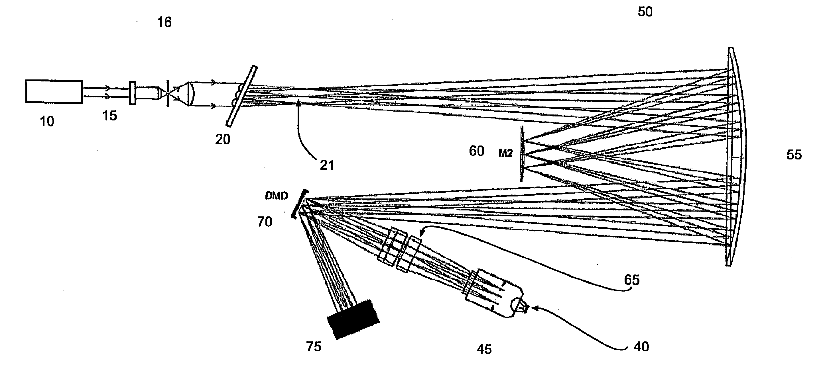
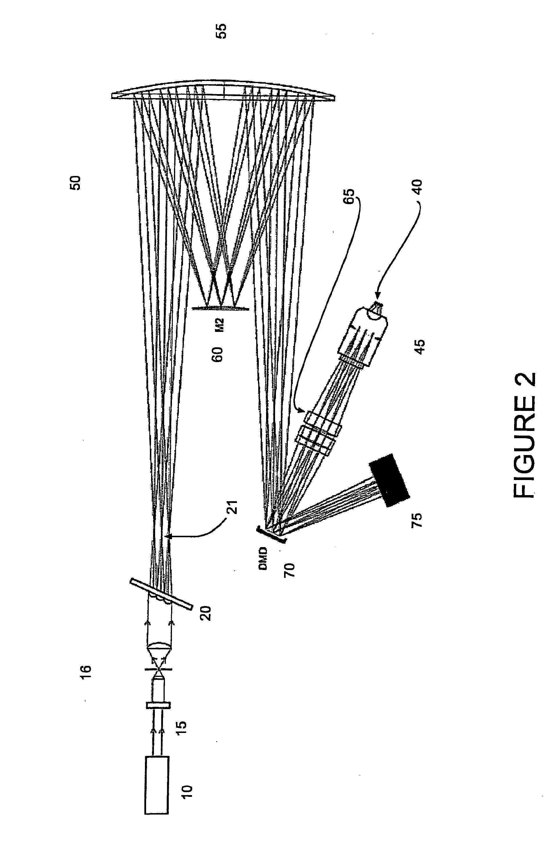
[0091]The optical system has been designed so that it can control individual traps and be integrated into a microfluidics system. In this design the primary multiple focal points matrix is formed and relayed into a specimen cell so that the entire trap formation is tied to the optical instrument and not to the specimen cell.

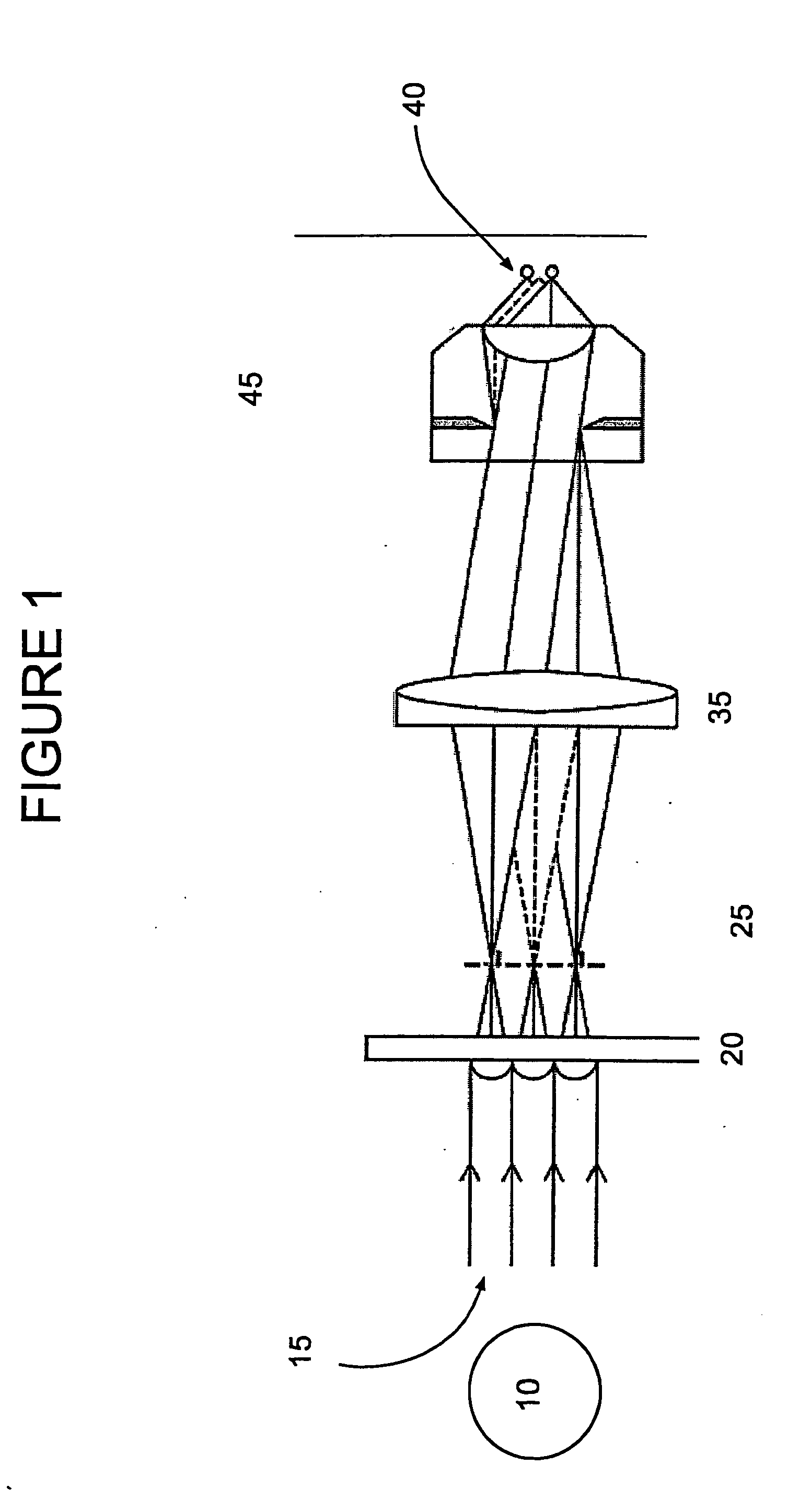
[0092]A simplified schematic of the optical system is provided in FIG. 1. A collimated beam of light enters a microlens array. The laser wavelength may be any from UltraViolet (UV) up to Near InfraRed (NIR). If the matrix of focal points formed by the microlens array is placed at the image plane of a microscope, it will be relayed onto an object plane. The microscope objective presents a very high NA lens, which is a necessary condition for efficient 3D trapping. The tube lens should be telecentric, which means it should present low aberrations for bundles of light that have their chief rays parallel to lens optical axis. In this case, the collimated pencils of l...


PUM


Abstract

Methods and devices are provided for the trapping, including optical trapping; analysis; and selective manipulation of particles on an optical array. A device parcels a light source into many points of light transmitted through a microlens optical array and an Offner relay to an objective, where particles may be trapped. Preferably the individual points of light are individually controllable through a light controlling device. Optical properties of the particles may be determined by interrogation with light focused through the optical array. The particles may be manipulated by immobilizing or releasing specific particles, separating types of particles, etc.

Description

GOVERNMENT RIGHTS[0001]This invention was made with government support under EB003985 awarded by the National Institutes of Health. The government has certain rights in the invention.BACKGROUND[0002]An Optical Tweezers system for three-dimensional trapping utilizes a laser light brought into a tight focus by a high NA lens. The focused light provides both gradient and scattering forces applied to a small particle which index of refraction is higher than that of a medium it is immersed into. When the particle reaches a point where both forces compensate each other, optical trapping is observed.[0003]It has been suggested that optical trapping, or tweezer systems could be applied to biological microparticles, for example see U.S. Pat. No. 6,416,190. Cell separation and phenotypic analysis are a rapidly growing area of biomedical and clinical development. Improved methods of separating a desired cell subset from a complex population permit the study and use of cells that have relativel...

Claims


Application Information

Patent Timeline
Patent Type & Authority Applications(United States)
IPC IPC(8): H01S1/00
CPCG02B17/0615G21K1/006G02B17/0636
Inventor WALT, DAVID R.FAUSTOV, ALEXEI R.
Owner TUFTS UNIV
Why Eureka
Try Eureka