Device And Method For Measuring Characteristics Of An Ion Beam

a technology of ion beam and characteristic measurement, applied in the field of hadron therapy, can solve the problems of insufficient type of detector for particular applications, inability to apply process to radiation delivery methods where collimators are used, and time-consuming procedures, etc., and achieve the effect of improving the capacity of said plurality of sensors

Inactive Publication Date: 2011-04-21
ION BEAM APPL
View PDF1 Cites 128 Cited by
  • Summary
  • Abstract
  • Description
  • Claims
  • Application Information

AI Technical Summary

Benefits of technology

[0019]The detector may further comprise a counter wedge located between said helical wheel and said plurality of conductive plates. Said counter wedge is then capable of compensating the gradient of said <<non-flat>> element when rotating, whereby it is possible to keep the same range shift over the full cross sectional area when the incident beam passes through said helical wheel.
[0020]The detector may further comprises grounded plates between said plurality of sensors and isolated from said plurality of sensors by means of insulating plates, for improving the capacity of said plurality of sensors, whereby allowing the detector to collect or integrate the charge deposited from said incoming particle beam.

Problems solved by technology

This procedure is however time consuming, and moreover, depends on the stability of the beam characteristics among measurements.
In addition, this process cannot be applied to radiation delivery methods where collimators are moved while irradiating, such as the virtual wedge method or IMRT, or for the case of active beams using a scanning technique.
However, this type of detector is not adequate for particular applications wherein the ratio between the span of measurable energy and the required resolution is high In such applications, in fact, it would be required a very great number of ionization chambers.
However, such a detector is very complex, difficult to assemble, sensitive and unreliable (due to shorts between plates) since it requires a lot of plates and a very thin insulator between said plates in order to obtain a better resolution (the resolution of a sensor being the smallest change it can detect in the quantity that it is measuring).
Such a device and method described in DE19606809C1 can however not be used to measure the energy and energy spread of a hadron beam due to the fundamental difference of energy loss in material between hadrons and photons.

Method used


Image

  • Device And Method For Measuring Characteristics Of An Ion Beam
  • Device And Method For Measuring Characteristics Of An Ion Beam
  • Device And Method For Measuring Characteristics Of An Ion Beam

Examples


embodiment 1

[0059]When the detector 600 is in use, the incident beam is scanned along the 300 mm over said wedge shaped element 604. While the beam is scanned over the wedge the total thickness of the detector 600 encountered by the particle beam varies accordingly. This is illustrated on FIG. 6 showing various beam crossing positions A, B, C, D, E, F, i.e. positions on the wedge where the beam is crossing the wedge. This can be a continuous position variation for crossing the wedge or a variation in small steps. As a consequence, different relative positions of the beam A,B,C,D,E,F over said wedge-shaped element 604 cause the beam to stop on different faraday cups of said stack. Since dimensions and number of faraday cups, as well as the water equivalent thickness of the materials of faraday cups and insulating plates, are known, it is possible to determine the characteristics of the particle beam by processing measurements of current coming from faraday cups by means of a processing unit. For...

second embodiment

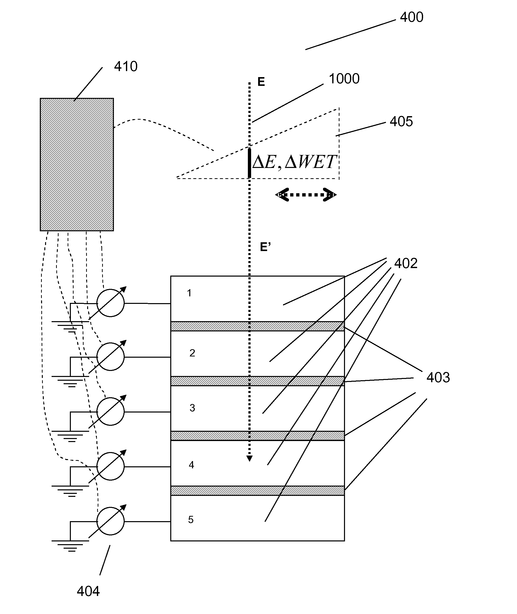
[0060]FIG. 8 shows a detector 800 according to the invention. Said detector 800 is also embedded in a housing 801 and comprises a stack of several parallel faraday cups 802 separated from each other by PMMA insulating plates 803. Detector 800 further comprises a rotating helical wedge 804 which is capable of rotating about an axis parallel to the direction of said ion beam 1000 and which is located between the radiation source and said stack of faraday cups 802. This rotating helical wedge 804 is made up of for example polycarbonate resin thermoplastic and has a non constant thickness so that it has a given thickness for a given rotation angle θ. Other materials could be used for the rotating wedge as well (carbon, . . . ).

[0061]Helical wedge 804 has either a stepped shape, as shown in FIG. 10, or an unidirectional constant gradient with a sharp edge at the end of a turn. In this manner it is possible to modulate the range of the incoming particle beam 1000 by simply rotating said h...

embodiment 2

[0062]For a nozzle using a scattering technique and where a rotating range modulator wheel is integrated in the nozzle to modulate the incoming beam, the principles of embodiment 2 can be used to measure the beam range. The range modulator of the nozzle can in this case play the role of rotating wedge 804.

[0063]According to a variant of the invention, as shown in FIG. 9, said stack of Faraday cups 902 are further separated from each other. As shown on FIG. 9 in-between the insulating plates 903 a thin grounded plates 904 is added. The use of such thin grounded plates 904 reduces influences of adjacent faraday cups as well as electrical influences from the surroundings and allows the detector 600, 800 providing different types of measurement, as follows. Faraday cups act in fact as collecting capacitors which collect or integrate the charge deposited from the incident particle beam 1000. In order to measure this charge each faraday cup can be discharged (e.g. to an integrating circui...


PUM


Abstract

The present invention relates to a detector for measuring characteristics of an energetic particle beam generated by a radiation source, the detector including means to vary the incoming particle beam energy; a plurality of sensors arranged in parallel; and processing means capable of processing signals coming from said sensors in correlation with said energy variation.

Description

TECHNICAL FIELD[0001]The invention relates to the field of Hadron Therapy, i.e. radiation therapy using strongly interacting particles. More particularly, the invention relates to a detector and method for measuring the range as well as the energy spread of a particle beam.DESCRIPTION OF RELATED ART[0002]It is now well established that hadrons (i.e. neutrons, protons, pions, ions such as carbon ions) have physical advantages with respect to X-rays or gamma rays in the field of radiation therapy. For example, hadrons of a given energy (i.e. forming a mono-energetic hadron beam), have a range which is defined as the penetration depth in matter and do not penetrate beyond that range, and furthermore, they deposit their maximum amount of energy in the so-called Bragg Peak, which corresponds to the point of greatest penetration of the radiation in the target volume. Since the Bragg peak position depends on the energy of the hadron beam, it is evident that by precisely controlling and mod...

Claims


Application Information

Patent Timeline
Patent Type & Authority Applications(United States)
IPC IPC(8): G01T1/29
CPCG01T1/2935
Inventor JONGEN, YVESARNOLD, MARTINCLAEREBOUDT, YVESPRIEELS, DAMIEN
Owner ION BEAM APPL
Why Eureka
Try Eureka