Ultra short baseline GNSS receiver

a receiver and ultra-short technology, applied in the field of global navigation satellite systems, can solve the problems that the system must still engage in processing intensive and time-consuming operations to solve the problem of 2-dimensionality

Active Publication Date: 2011-04-21
NOVATEL INC
View PDF13 Cites 15 Cited by
  • Summary
  • Abstract
  • Description
  • Claims
  • Application Information

AI Technical Summary

Benefits of technology

[0008]A GNSS receiver utilizes an antenna structure in which two antennas are spaced apart by less than one wavelength of the GNSS satellite carrier signals of interest. The receiver calculates azimu

Problems solved by technology

However, the system must still engage in processing intensive a

Method used


Image

  • Ultra short baseline GNSS receiver
  • Ultra short baseline GNSS receiver
  • Ultra short baseline GNSS receiver

Examples


Embodiment Construction

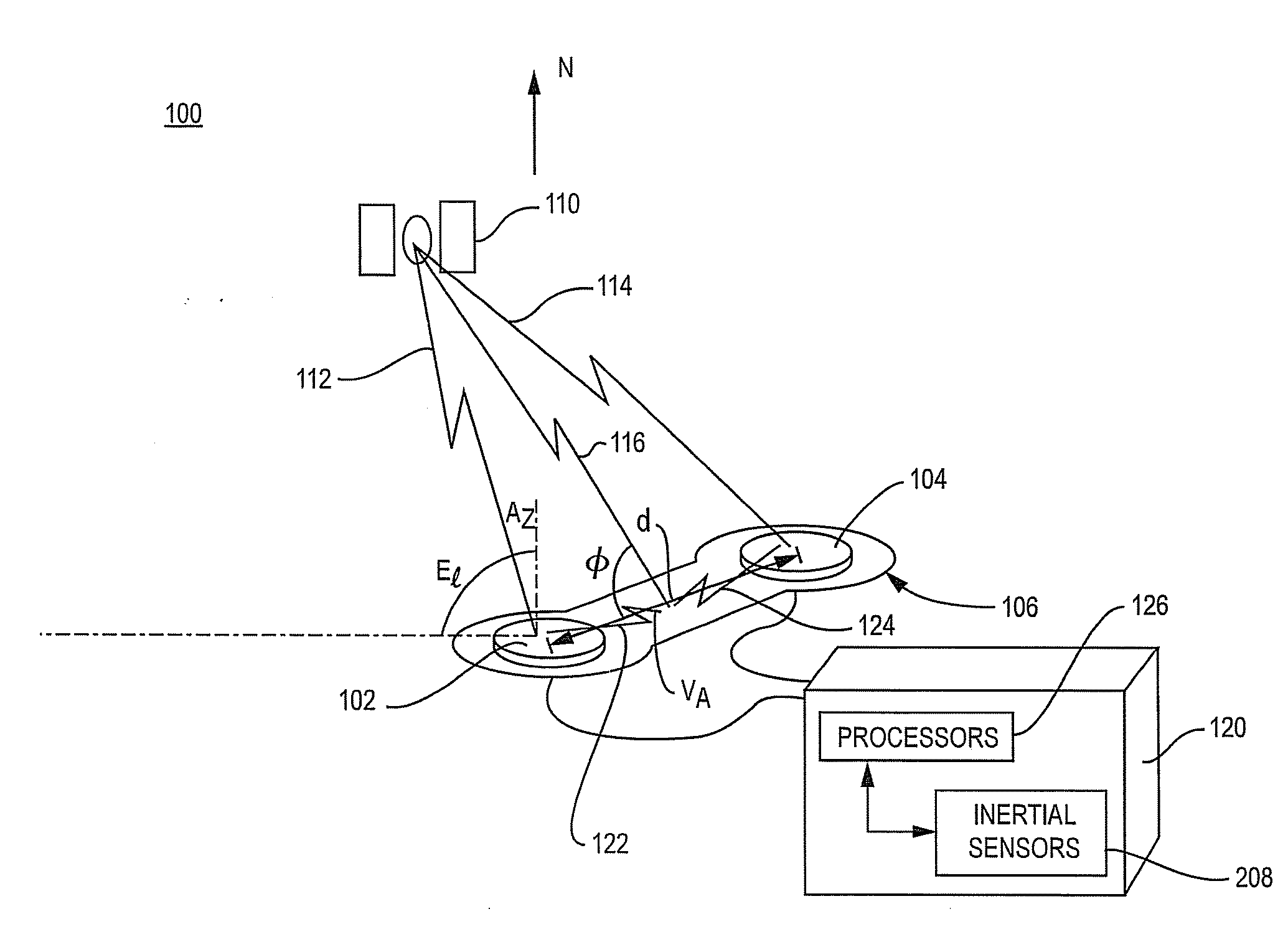
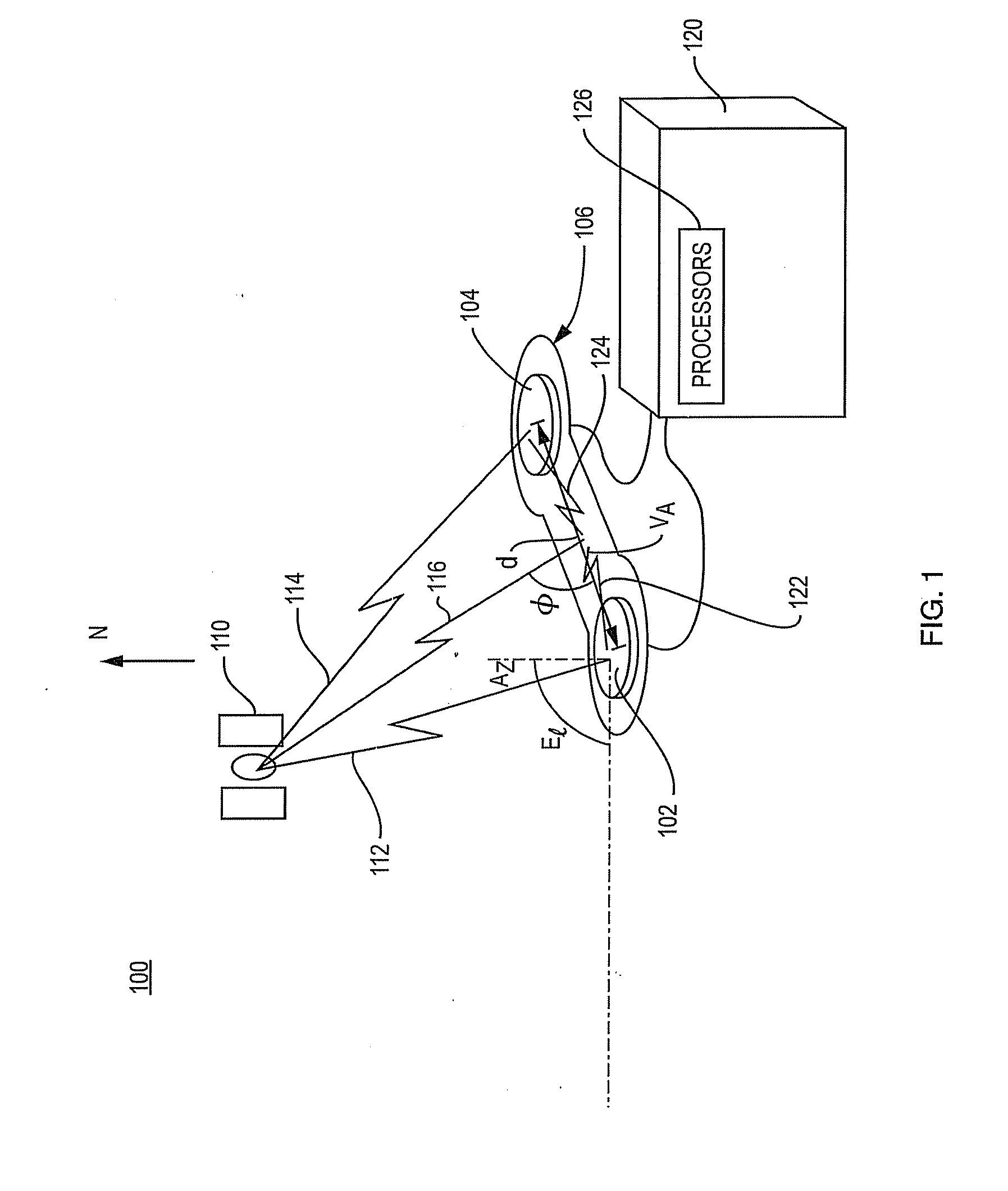
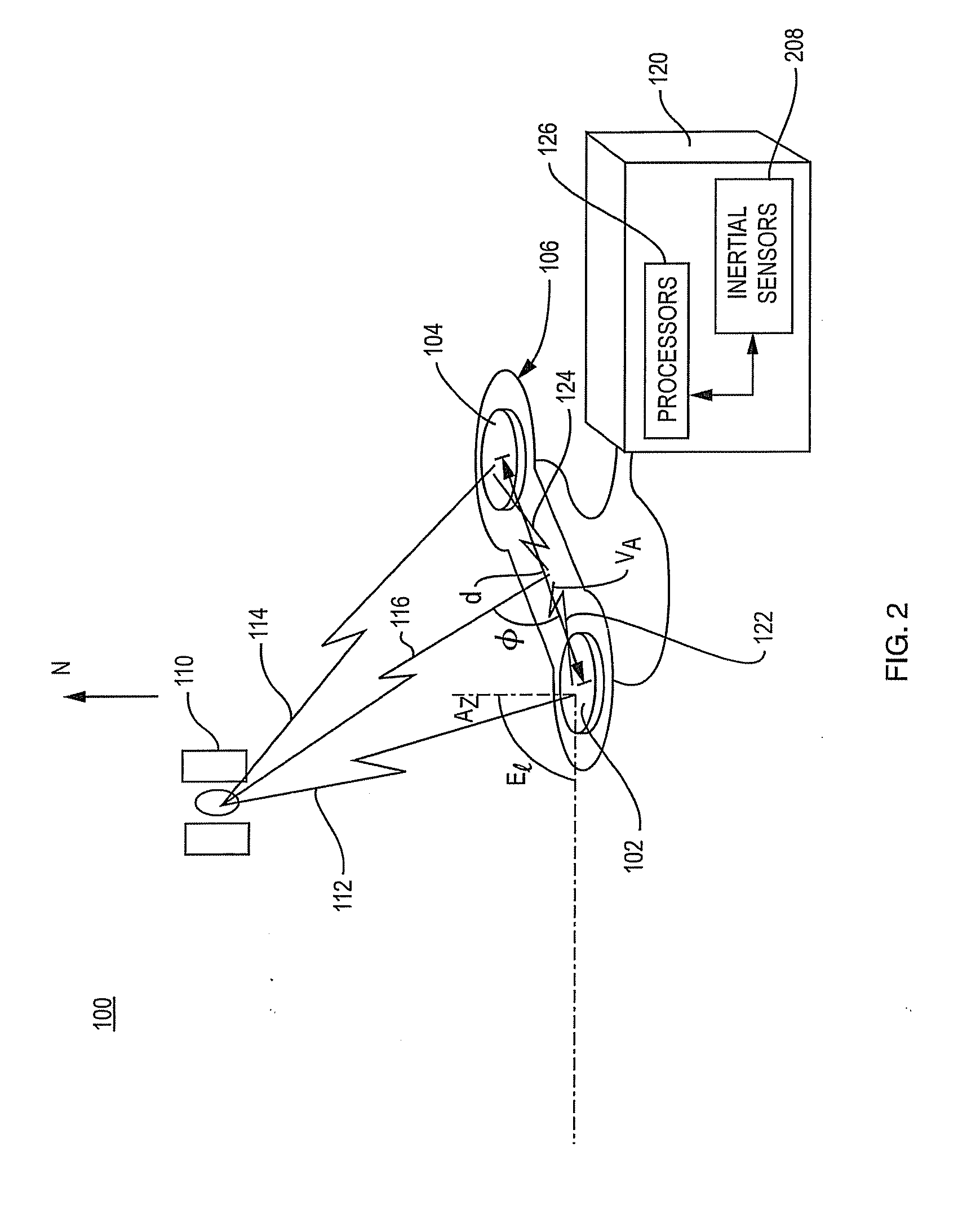
[0015]FIG. 1 is a schematic illustration of an ultra-short baseline system 100 that receives GNSS satellite signals transmitted by a GNSS satellite 110. More specifically, the system 100 of FIG. 1 includes an antenna structure 106106 that consists of dual antennas 102 and 104 that are mounted on a rigid frame 106 and a receiver 120 with one or more processors 126 that processes the signals received by the antennas. The antennas reside a distance “d” apart, where d is constrained to be less than 1 wavelength of the GNSS satellite carrier signals of interest. The spacing d may, for example, be less than 19 cm for a system that operates with GPS L1 satellite carrier signals.

[0016]The signals from the GNSS satellite 110 are represented schematically as signal path 112, which is received by antenna 102, and signal path 114, which is received by antenna 104. The lengths of the two paths differ because of the different locations of the respective antennas. The signals received by the dual ...


PUM


Abstract

A GNSS receiver utilizes an antenna structure that two or more antennas that are spaced apart from their neighboring antennas by less than 1 wavelength of a GNSS satellite carrier signal of interest. The receiver calculates the orientation of the antennas directly from differences in the carrier phase angles measured at the two antennas, without resolving integer carrier cycle ambiguity.

Description

BACKGROUND OF THE INVENTION[0001]1. Field of the Invention[0002]This invention relates generally to global navigation satellite systems (GNSS) and more particularly to short baseline receivers.[0003]2. Background Information[0004]Short baseline real time kinematic (RTK) systems typically operate with a base GNSS receiver and a rover GNSS receiver that are separated by a small number of kilometers, for example, less than 10 kilometers. The base receiver, which is in a known position, makes carrier phase measurements using GNSS signals transmitted from GNSS satellites in view and calculates pseudoranges from the respective satellites. The base receiver then determines differences between the pseudoranges calculated using the satellite signals and the ranges based on the known position of the receiver and the known locations of the satellites, to determine pseudorange correction information. The base receiver operating in a known manner broadcasts the RTK information, that is, the rang...

Claims


Application Information

Patent Timeline
IPC IPC(8): G01S19/54G06F15/00
CPCG01S19/54
Inventor FENTON, PATRICK C.
Owner NOVATEL INC
Why Eureka
Try Eureka